Removal and installation
− Before starting to remove parts, carry out the following operations:
- A) Remove the side door trim.
- b) Remove the waterproof film of the side door.
- Parts are removed in the order of the numbers shown in the figure "Removing the lock and side door handle".
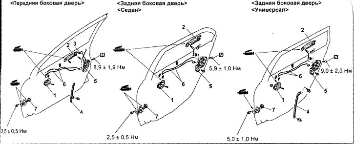
Removing the lock and side door handle. 1 - inside handle for opening the side door (remove the waterproof film of the side door); 2 - outside handle of the side door; 3 - larva of the lock of the side door; 4 - rear lower glass guide of the side door; 5 - side door lock assembly; 6 - pull rod assembly; 7 - side door opening limiter.
− Install parts in the reverse order of removal.
− When installing parts, pay attention to the following operations:
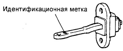
1. Installing the side door opening limiter.
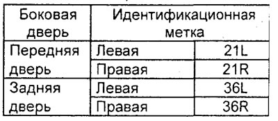
Install the side door opening limiter so that the identification mark is located at the top.
Table of identification marks.
2. Installing the rear lower side door glass guide.
Securely insert the rear lower glass guide into the rear side door glass guide.
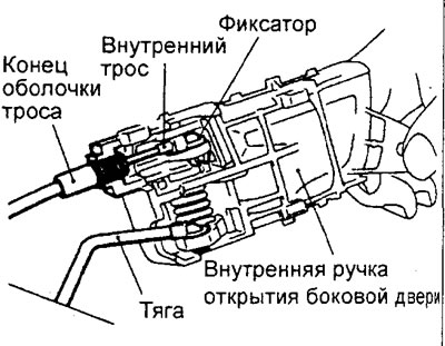
3. Installing the inside handle for opening the side door.
A) To install the inner cable, follow these steps:
- - Secure the end of the inner cable to the inner handle with the lock.
- - Set the side door lock button to the position "blocked".
- - Attach the end of the cable sheath securely to the inside handle for opening the side door.
- - Install the retainer on the inner cable.
b) Install the side door latch lock rod into the inside side door opening handle.
V) Install the inner side door opening handle on the door.
− After completing the installation of the parts, perform the following operations:
- A) Check the travel of the inside and outside side door handles.
- b) Install the side door waterproof film.
- V) Install the side door trim.
Examination (models with central locking)
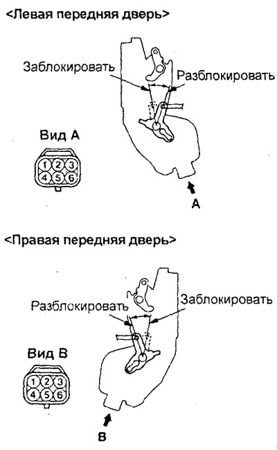
1. (Left front door) Checking the front side door lock actuator.
A) Install the side door lock rod (front left) into position "LOCKED", apply battery voltage to terminal "4" connector and check that the lock lever moves to the position "UNLOCKED", when output "6" connector connected to "weight".
b) Set the lock rod of the side door lock to the position "UNLOCKED", apply battery voltage to terminal "6" connector and check that the lock lever moves to the position "LOCKED", when output "4" connector connected to "weight".
2. (Right front door) Checking the front side door lock actuator.
A) Install the side door lock rod (front right) into position "LOCKED", apply battery voltage to terminal "6" connector and check that the lock lever moves to the position "UNLOCKED", when output "4" connector connected to "weight".
b) Set the lock rod of the side door lock to the position "UNLOCKED", apply battery voltage to terminal "4" connector and check that the lock lever moves to the position "LOCKED", when output "6" connector connected to "weight".
V) Check for continuity between terminals "2" And "3" connector. when the lock is in position "UNLOCKED".
G) Check for continuity between terminals "1" And "3" connector when the lock is in position "LOCKED".
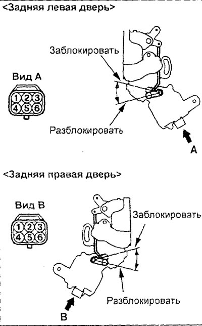
3. (Right rear door) Checking the rear side door lock actuator.
A) Set the lock rod of the side door lock to the position "LOCKED", apply battery voltage to terminal "3" connector and check that the lock lever moves to the position "UNLOCKED", when output "2" connector connected to "weight".
b) Set the lock rod of the side door lock to the position "UNLOCKED", apply battery voltage to terminal "2" connector and check that the lock lever moves to the position "LOCKED", when output "3" connector connected to "weight".
4. (Left rear door) Checking the rear side door lock actuator.
A) Set the lock rod of the side door lock to the position "LOCKED", apply battery voltage to terminal "3" connector and check that the lock lever moves to the position "UNLOCKED", when output "2" connector connected to "weight".
b) Set the lock rod of the side door lock to the position "UNLOCKED", apply battery voltage to terminal "2" connector and check that the lock lever moves to the position "LOCKED", when output "3" connector connected to "weight".