



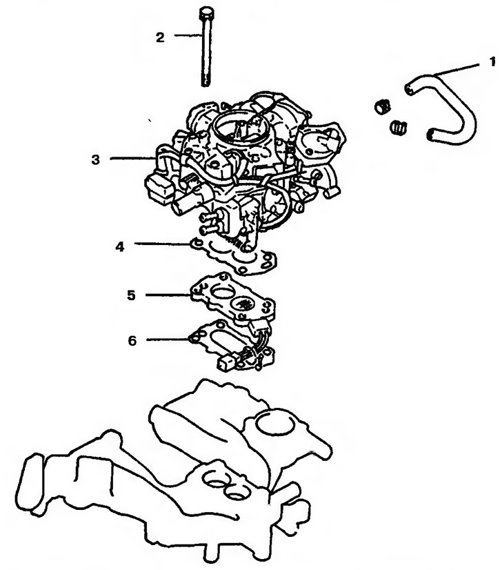
Figure 10.69. Assembled carburetor: 1 - Cooling system pipe; 2 - Bolt; 3 - Carburetor; 4, 6 - Gasket; 5 - Element for heating the combustible mixture when starting a cold engine (only for engines 4G1 and 4G3)
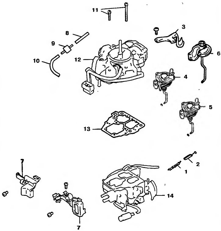
Figure 10.70. Disassembled carburetor: 1 - Throttle valve return spring; 2 - Rubber damper; 3 - Throttle valve return spring bracket; 4 - Throttle valve closing drive with accelerator; 5 - Throttle closing drive; 6 - Throttle valve outlet; 7 - Bracket; 8, 10 - Hoses; 9 - Vacuum retarder valve; 11 - Bolts; 12 - Carburetor cover; 13 - Carburetor cover gasket; 14 - Carburetor body and throttle body
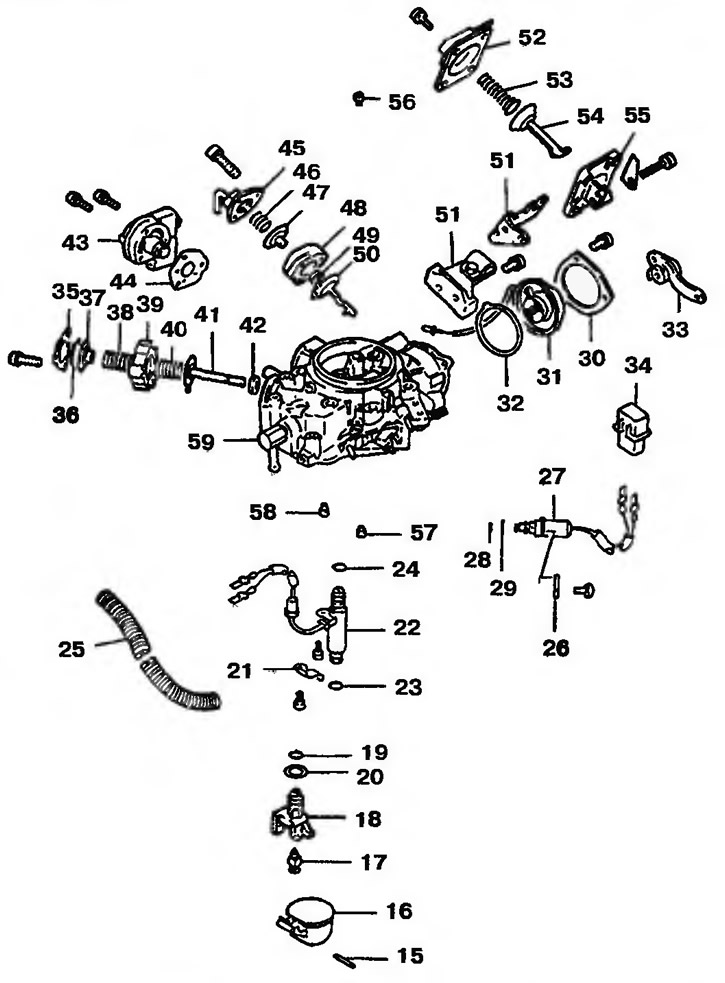
Figure 10.71. Disassembled carburetor: 15 - Pin; 16 - Float; 17 - Needle valve; 18 - Needle valve seat; 19, 23, 24, 28, 29 - Sealing rings; 20, 30, 32, 44 - Gaskets; 21,26 - Fixators; 22 - Lambda control electromagnetic valve; 25 - Tube; 27 - Dosing solenoid valve; 31 - Bimetallic element; 33 - Lever and gear; 34 - Wiring connector; 35 - Lid; 36, 41, 47, 50, 54 - Membranes; 37 - Spring diaphragm; 38, 40, 46, 49, 53 - Springs; 39, 48, 55 - Cases; 42 - Valve; 43 - Fuel mixture control valve; 45, 52 - Lids; 51 - Bracket; 56 - Air jet of the main fuel metering system; 57 - Idle jet (primary); 58 - Idle jet (secondary); 59 - Carburetor cover
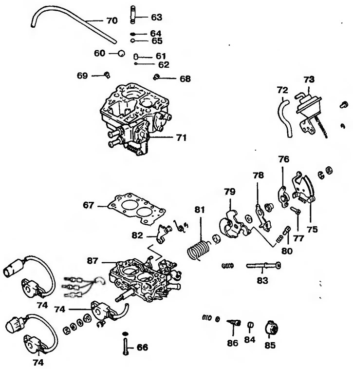
Figure 10.72. Disassembled carburetor: 60 - Steel Ball; 61 - Cargo; 62, 65 - Balls; 63 - Threaded plug; 64 - Sealing ring; 66 - Bolt; 67 - Gasket; 68 - Main fuel jet (primary); 69 - Main fuel jet (secondary); 70 - Pipeline; 71 - Carburetor body; 72 - Vacuum tube; 73 - Vacuum ignition advance regulator membrane mechanism; 74 - Throttle position sensor; 75 - Accelerator control rod lever; 76 - Cam follower; 77 - Adjusting screw for fast idle speed; 78 - Free Lever; 79 - Retainer; 80 - Idle speed adjusting screw (No. 2); 81 - Spring; 82 - Auxiliary (secondary) lever; 83 - Idle speed adjusting screw (No. 1); 84 - Plug; 85 - Throttle lever stop screw; 86 - Combustible mixture adjustment screw; 87 - Throttle body
(The source of the article is available at: MITSUBISHIMAN.ru)