
- 1. Valve and throttle shaft;
- 2. Painted adjustment screw;
- 3. Carburetor body.
Float chamber
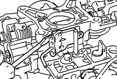
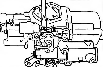
1. The float chamber is held firmly by a gasket. Insert the tip of a screwdriver between the carburetor body and the float chamber and, while pressing lightly on the float chamber, gently pry it up (pic. 10.36). The gasket can only be removed when the float chamber is removed. Therefore, do not attempt to remove the gasket together with the float chamber.
Pic. 10.36. Removing the float chamber
Adapter
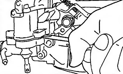
2. Do not attempt to remove the adapter in one go as it is held tightly by the gasket. Insert the tip of a screwdriver between the carburetor body and the adapter and, while pressing lightly on the adapter, carefully lift it up (pic. 10.37).
Pic. 10.37. Removing the adapter
Return spring
3. Hook the metal wire on the return spring and remove it (pic. 10.38).
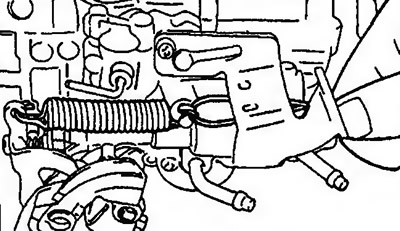
Pic. 10.38. Removing the return spring
Speed boost eccentric, economizer rod, spring and seal
4. Remove the snap-on bracket (pic. 10.39). Remove the traction system from it. Loosen the adjusting screw for the idle speed eccentric to allow the economizer link eccentric to be removed. Remove the economizer link, spring and seal.
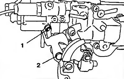
Pic. 10.39. Removing the speed boost eccentric, economizer rod, spring and seal. 1 - Snap-in bracket; 2 - Adjusting screw of the eccentric for increasing the idle speed
Compensator
5. The gasket is firmly held in place. Pry it out with a screwdriver (pic. 10.40).
Pic. 10.40. Removing the compensator
Lock plate
6. A bolt is screwed into the locking plate (thread diameter - 4 mm, length - 20 mm or more) and it comes off with pliers and wrench (pic. 10.41).
Attention! The wrench is installed across the holes for the air filter support mounting bolts.
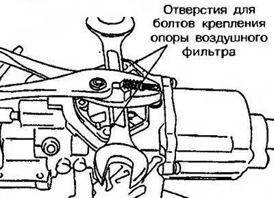
Pic. 10.41. Removing the lock plate
Diffuser, spring and piston
7. When removing the diffuser from the carburetor body, it must not be pressed out and excessive force must not be used. The diffuser can be easily removed by turning it clockwise or counterclockwise (pic. 10.42).
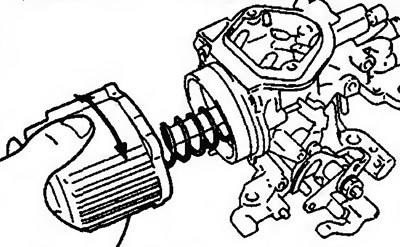
Pic. 10.42. Removing the diffuser
8. Slightly lift the metering pin with your finger so that it does not block the main fuel jet, and pull the diffuser piston to the right corner (pic. 10.43).
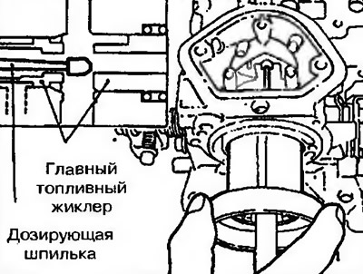
Pic. 10.43. Removing the piston and spring
Attention! For the effective performance of the carburetor, uniform sliding movements of the diffuser piston are important. Also, the inner surface of the piston and diffuser must not be damaged. As soon as the metering pin is removed from the piston, it immediately comes off. Therefore, the pin cannot be removed from the diffuser piston. The dosing pin can be easily deformed. Therefore, after removal, it should be handled with extreme care.
Stub
9. The plug is removed with a cutter (pic. 10.44).
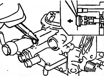
Pic. 10.44. Removing the plug
Screw for adjusting the composition of the combustible mixture (MAS)
10. Using a MD998299 screwdriver, remove the idle speed limiter and air mixture adjustment screw (MAS) (pic. 10.45 am).
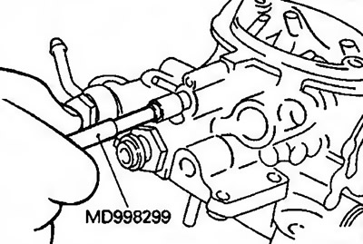
Pic. 10.45. Removing the air mixture adjustment screw (MAS)
Adjusting screw of the main fuel jet
11. Hold the adjusting screw of the main fuel jet with tongs and turn it counterclockwise so that it can be removed from the protective cap (pic. 10.46).
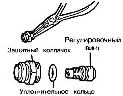
Pic. 10.46. Removing the adjusting screw of the main fuel jet
12. To remove the lock plate from the protective cap of the main fuel jet, use a punch with a diameter of 5 mm, a 21 mm socket wrench and a hammer (pic. 10.47).
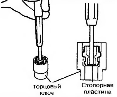
Pic. 10.47. Removing the lock plate from the protective cap of the main fuel jet
Pin and gasket
13. Make sure that no paint particles get into the carburetor by removing the yellow paint around the pin.
14. The pin and gasket are carefully removed so that the main fuel jet does not pop out.
Attention! Gasket may stick due to yellow paint.
Throttle valve closing actuator (automatic transmission)
15. Check the throttle closing actuator diaphragm for damage. Using a manual vacuum pump, create a vacuum of 500 mmHg. and make sure the vacuum is maintained (pic. 10.48). When creating a vacuum, the throttle closing actuator rod should rise. If the vacuum is not held, the diaphragm is damaged. In this case, the throttle closing actuator must be replaced.
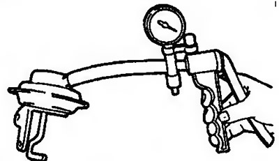
Pic. 10.48. Checking the throttle closing actuator diaphragm