



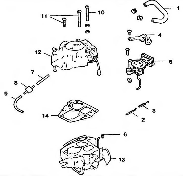
Figure 10.25a. Type "C" carburetor: 1 - Cooling system pipe; 2 - Throttle return spring; 3 - Rubber shock absorber; 4 - Throttle return spring mounting bracket; 5 - Throttle closing damper; 6 - Retainer; 7, 9 - Tubes; 8 - Retarding valve; 10 - Carburetor cover mounting bolt; 11 - Bolt with washer; 12 - Carburetor cover; 13 - Float chamber and throttle body; 14- Gasket
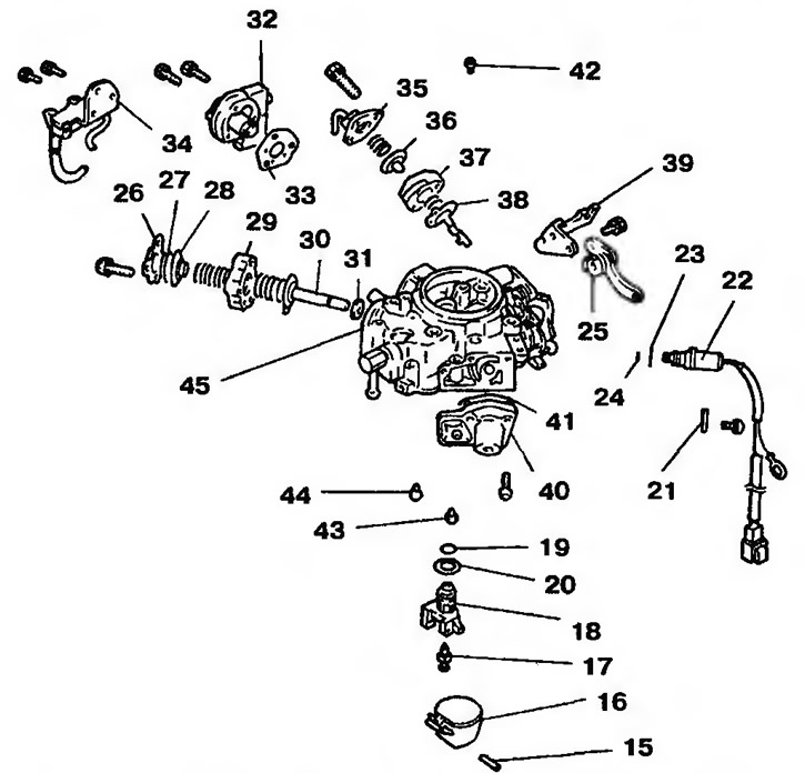
Figure 10.256. Carburetor cover: 15 - Pin; 16 - Float; 17 - Needle valve; 18 - Needle valve seat; 19, 33, 41 - Gaskets; 20, 23, 24 - Sealing rings; 21 - Retainer; 22 - Solenoid shut-off valve; 25 - Lever; 26, 35 - Lids; 27, 30, 36, 38 - Membranes; 28 - Valve; 29 - Spring seat; 31 - Valve; 32 - Fuel mixture quantity adjustment valve; 34 - Idle speed compensator; 37 - Body; 39 - Bracket; 40 - Servo valve; 42 - Main air jet; 43 - Idle jet (primary); 44 - Idle jet (secondary); 45 - Carburetor cover
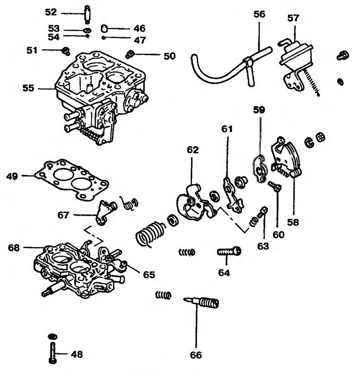
Figure 10.25c. Float chamber and throttle body: 46 - Weight; 47, 54 - Balls; 48 - Bolt; 49 - Gasket; 50, 51 - Main jets; 52 - Cork; 53 - Sealing ring; 55 - Float chamber; 56 - Tube; 57 - Decompression chamber; 58 - Throttle lever; 59 - Cam follower; 60, 63, 64 - Idle speed adjusting bolts; 61 - Lever; 62 - Bracket; 65 - Throttle closing damper adjusting bolt; 66 - Fuel mixture quantity adjustment bolt; 67 - Secondary lever; 68 - Throttle body
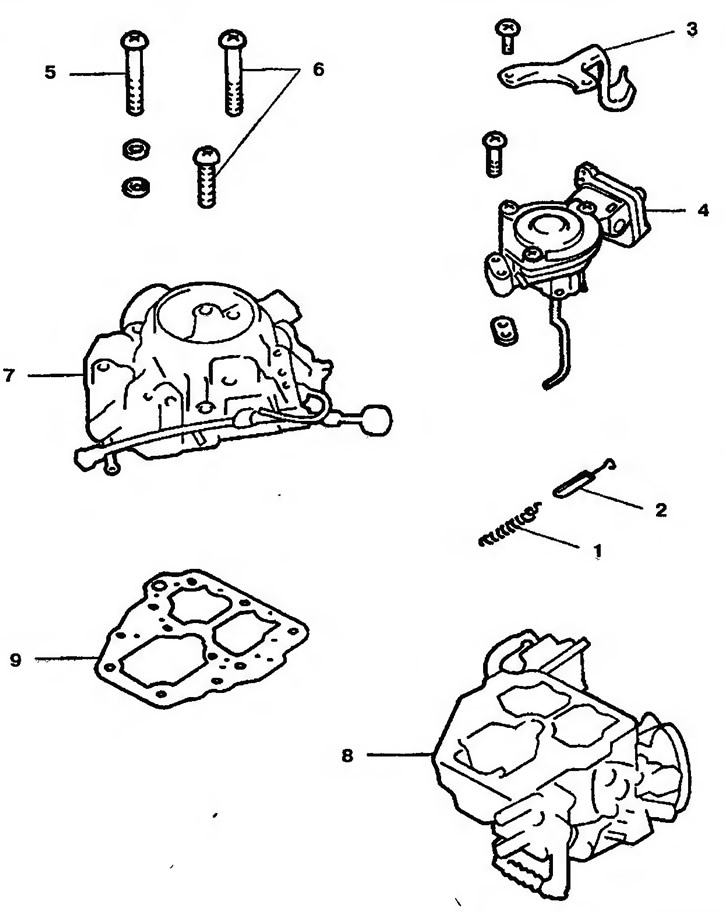
Figure 10.26a. Type "D" carburetor: 1 - Throttle return spring; 2 - Rubber shock absorber; 3 - Return spring bracket; 4 - Throttle closing damper; 5 - Carburetor cover mounting bolt; 6 - Bolt with washer; 7 - Carburetor cover; 8 - Float chamber; 9 - Gasket
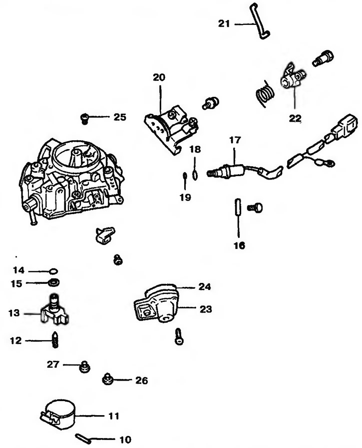
Figure 10.26. Carburetor cover: 10 - Pin; 11 - Float; 12 - Needle valve; 13 - Needle valve seat; 14, 15, 18, 19 - Sealing rings; 16 - Retainer; 17 - Solenoid shut-off valve; 20 - Bracket; 21 - Air damper rod; 22 - Choke lever; 23 - Servo valve; 24 - Gasket; 25 - Main air jet; 26 - Idle jet (primary); 27 - Idle jet (secondary)
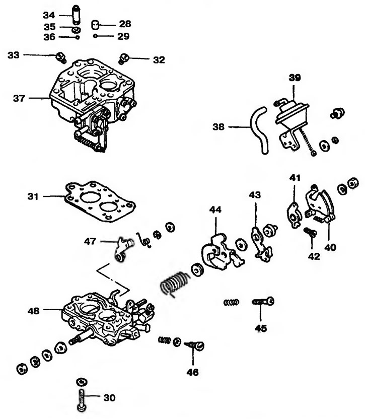
Figure 10.26c. Float chamber and throttle body: 28 - Weight; 29, 36 - Balls; 30 - Bolt; 31 - Gasket; 32, 33 - Main jets; 34 - Cork; 35 - Sealing ring; 37 - Float chamber; 38 - Tube; 39 - Decompression chamber; 40 - Throttle lever; 41 - Cam follower; 42 - Adjusting bolt; 43 - Lever; 44 - Bracket; 45 - Idle speed adjusting bolt; 46 - Fuel mixture quantity adjustment bolt; 47 - Secondary lever; 48 - Throttle body
Disassembly
1. Unscrew the five mounting bolts (four 65 mm long and one 45 mm) of the carburetor cover and remove the carburetor body (Figure 10.27). Be sure to remove the bolt that is in the countersunk threaded hole between the primary and secondary threaded mounting holes.
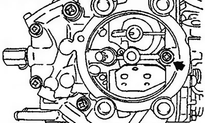
Figure 10.27. Removing the carburetor cover
2 The carburetor cover has a gasket. Therefore, in order not to apply force, use a screwdriver, inserting it into the gap and lifting the cover to facilitate removal (Figure 10.28).
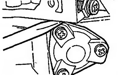
Figure 10.28. Use a screwdriver to remove the carburetor cover
3. Using two screwdrivers, pry the valve seat by the protruding edges to remove it (Figure 10.29).
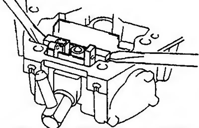
Figure 10.29. Using two screwdrivers, remove the valve seat
Caution: When removing the valve seat, do not damage the carburetor cover.
4. Before removing the lever, pay attention to the installation marks (Figure 10.30).
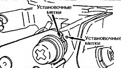
Figure 10.30. Marks for installing the lever
5. Remove the idle speed limiter valve and the fuel mixture quantity adjusting bolt using a special tool (Figure 10.31).
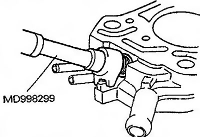
Figure 10.31. Remove the idle speed limiter valve and the fuel mixture quantity adjusting bolt
Examination
6. Check the fuel and air passages for blockages. If they are blocked, wash the blocked parts (injectors, etc.) with detergent or special cleaning liquid and blow them out with compressed air. Do not use wires or metal rods or objects for cleaning.
7. Check the membranes, sealing rings and springs for damage.
8. Check the fuel inlet filter (located above the needle valve) for blockages or damage.
The text of the article was obtained from the website: MitsubishiMan.ru
9. Check the operation of the float. Check the lever and float for deformation and damage.
10. Check the throttle valve and traction system. If they move stiffly, clean the parts and apply a thin layer of engine oil to their rollers.
11. Check the carburetor cover and float chamber for damage and cracks.
Installation
12. Make sure that the jet is installed correctly in the appropriate position. The applied slots serve to identify the jets (Figure 10.32).
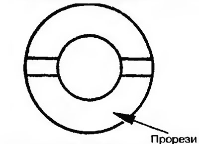
Figure 10.32. Jet identification slots
Checking and adjusting the throttle clearance at high idle speed (type "C")
13. Before checking and adjusting, the carburetor must be placed in a room with a temperature below 18°C for at least an hour and then in a room with a temperature of about 23°C for at least an hour.
14. Please note: the alignment mark on the lever must coincide with the center punch mark on the pusher (Figure 10.33).
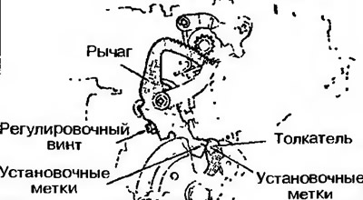
Figure 10.33. Aligning the marks on the lever with the center punch mark on the pusher
15. Measure the gap between the primary valve and the carburetor wall (Figure 10.34).
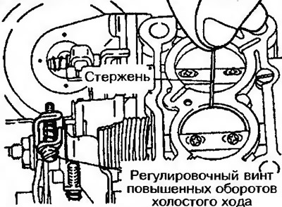
Figure 10.34. Checking the clearance between the primary valve and the carburetor wall
16. If the gap does not correspond to the permissible values, adjust it with the idle speed adjusting bolt (Figure 10.35).
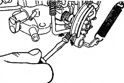
Figure 10.35. Adjusting the clearance with the idle speed adjusting bolt
| Direction of rotation of the adjusting bolt | Gap | Notes |
| Clockwise | Big | It is increasing |
| Counterclockwise | Small | Decreases |