
Attention! Be careful not to brush the piston, diffuser surface, carburetor body bore, or main jet. Do not wash the compensator. Make sure that dust does not get into the ventilation holes. Do not bend the main fuel jet or metering pin to avoid damaging them.
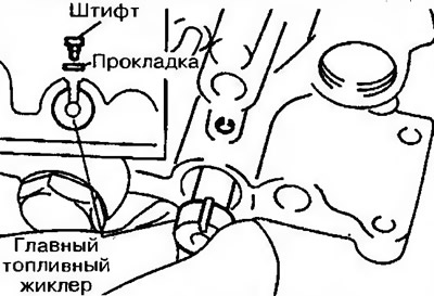
Main fuel jet
16. Install two O-rings on the jet and insert them together with the spring into the carburetor body.
17. Using a Phillips screwdriver, the main fuel jet is pressed into the carburetor body, the slot of the jet is aligned with the pin hole of the carburetor body, and then the pin with the gasket is installed (pic. 10.40).
Pic. 10.49. Install two o-rings on the jet and insert them together with the spring into the carburetor body
18. The jet is pressed with a Phillips screwdriver so that you can make sure it moves evenly (pic. 10.50).
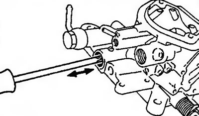
Pic. 10.50. The jet is pressed with a Phillips screwdriver so that you can make sure it moves evenly
Adjusting screw of the main fuel jet
19. The adjusting screw is screwed into the jet plug with your fingers.
20. Using a screwdriver, the plug of the adjusting screw of the main fuel jet is twisted by turning it counterclockwise (fig.10.51).Do not overtighten the screw to avoid damaging the thread.
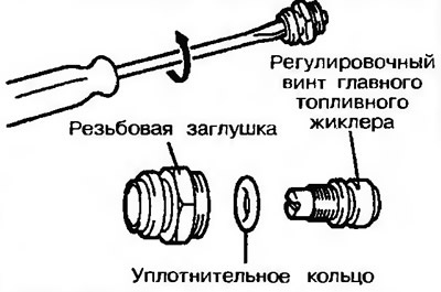
Pic. 10.51. Using a screwdriver, the plug of the adjusting screw of the main fuel jet is twisted by turning it counterclockwise
21. The threaded plug of the main fuel jet is installed through the gasket into the carburetor body.
22. Initial adjustment of the adjusting screw of the main fuel jet is made using a caliper (pic. 10.52).
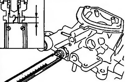
Fig.10.52. The initial adjustment of the adjusting screw of the main fuel jet is made using a caliper
Attention! The setting parameters are given in the maintenance data table.
Screw for adjusting the composition of the combustible mixture
23. A wire is used to guide the plate. The plate is installed with its rubber part inside (pic. 10.53). Then they are installed in the following order: spring, stud and screw for adjusting the composition of the combustible mixture (pic. 10.53). The initial setting of the screw for adjusting the composition of the combustible mixture is made using a caliper (pic. 10.54).
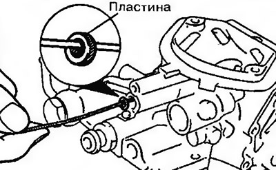
Pic. 10.53. A wire is used to guide the plate. The plate is installed with its rubber part inside | 
Pic. 10.54. The initial setting of the screw for adjusting the composition of the combustible mixture |
Diffuser piston
24. Carefully install the piston into the carburetor body without bending the metering pin. Do not use excessive force when installing the piston.
Attention! If the tip of the metering pin is blocked by the main fuel jet and cannot be inserted, it can be lifted slightly with your finger (pic. 10.55).
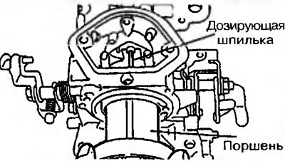
Pic. 10.55. Carefully install the piston into the carburetor body without bending the metering pin. If the tip of the metering pin is blocked by the main fuel jet and cannot be inserted, it can be lifted slightly with your finger
Pin, o-ring and retaining plate
25. Align the slot in the diffuser piston with the hole in the carburetor body and insert the pin with a screwdriver so that it fits into the piston groove. Make sure that the diffuser piston does not scroll (pic. 10.56).
Pic. 10.56. Align the slot in the diffuser piston with the hole in the carburetor body and insert the pin with a screwdriver so that it fits into the piston groove
26. Install the o-ring. Tighten a 4 mm bolt on the lock plate and hammer in the plate until it is firmly aligned with the surface of the carburetor body (pic. 10.57).
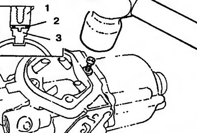
Pic. 10.57. Install the sealing ring. Tighten the 4 mm bolt on the stop plate and hammer in the plate until it is firmly aligned with the surface of the carburetor body. 1 - Locking plate; 2 - O-ring; 3 - Pin
Compensator
27. First, lightly tighten the three bolts, and then tighten them. At the same time, observe the order of their tightening (rice, 10.58).
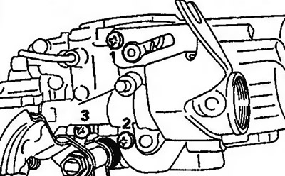
Pic. 10.58. Lightly tighten the three bolts first, then tighten them. At the same time, observe the order of their tightening
Economizer rod
28. Set the rod in the right direction (pic. 10.59).
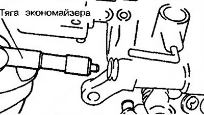
Pic. 10.59. Installing the economizer rod in the correct direction
Return spring
29. Attach the inner return spring to the outer. Attach the return spring with a metal wire (pic. 10.60).
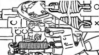
Pic. 10.60. Attach the inner return spring to the outer. Attach the return spring with a metal wire
Float and pin
30. When installing the float and pin, adjust the height of the float (pic. 10.61).
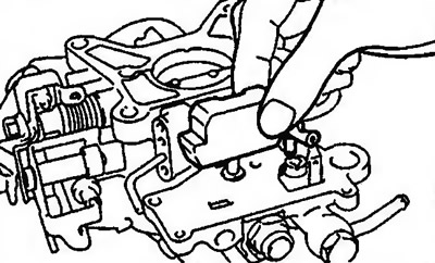
Pic. 10.61. When installing the float and pin, adjust the height of the float
Float height adjustment
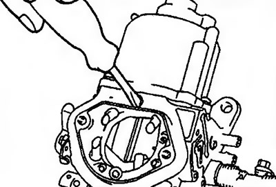
31. Turn the carburetor body and remove the hook mounted on the needle valve (pic. 10.62).
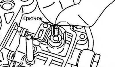
Pic. 10.62. Turn the carburetor body and remove the hook mounted on the needle valve
32. Install float and float pin.
33. Lightly press the float up until it stops (big arrow in Fig. 10.63) and measure the clearance between the needle valve and the float arm (small arrow in fig. 10.63). Nominal value: 1.0 mm.
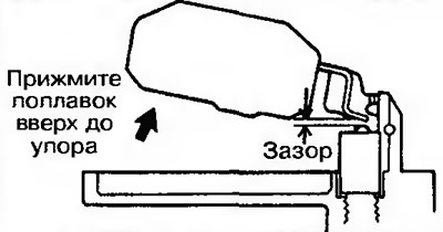
Pic. 10.63. Lightly press the float up until it stops (big arrow) and measure the clearance between the needle valve and the float arm (small arrow)
34. If the gap does not correspond to the nominal value, it must be adjusted by bending the lever (pic. 10.64). When bending, the gap increases, when straightened, it decreases.
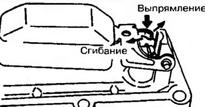
Pic. 10.64. Float adjustment
35. Release the float so that it hangs down and measure the distance between the float and the carburetor body (pic. 10.65). Nominal value: 4.3 mm.
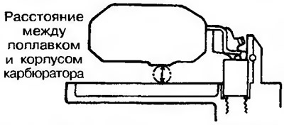
Pic. 10.65. Release the float so that it hangs down and measure the distance between the float and the carburetor body
36. If the distance does not correspond to the nominal, it can be adjusted by bending the element (arrow), shown in fig. 10.66.
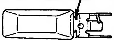
Pic. 10.66. If the distance does not correspond to the nominal, it can be adjusted by bending the element (arrow)
37. Remove the float and install the hook on the needle valve.
38. Install the float by hanging it with a prong on the hook.