



2. The heater is subject to testing for electrical conductivity (Figure 10.3). Specified value: electrical conductivity is present at a resistance of about 1 Ohm at a temperature of 20°C.
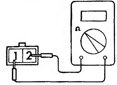
Figure 10.3. Checking the heater conductivity
3. Connect battery voltage to the heater terminals and make sure it heats up (Figure 10.4).
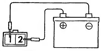
Figure 10.4. Checking the heater's functionality
4. Using the threaded holes for installing the carburetor, install two guide rods on the intake manifold (threaded part diameter - 6.6 mm, rod diameter - 8 mm). Place the rods diagonally relative to each other (Figure 10.5).
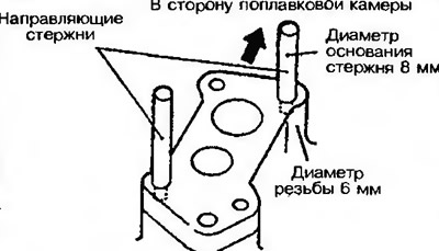
Figure 10.5. Install the two guide rods to properly install the carburetor
5. Install the gaskets and carburetor on the guide rods on the intake manifold (Figure 10.6, a, b).
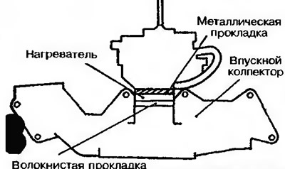
Figure 10.6a. Installing carburetor types "A" and "B" | 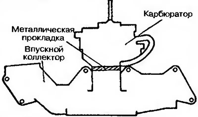
Figure 10.6b. Installing carburetor type "C" and "D" |
[The text of the article was taken from the website: MITSUBISHIMAN]
Caution: Do not move the carburetor after installation.
7. Install the mounting bolts into both free threaded holes and tighten them by hand.
8. Unscrew the guide rods and install the other two mounting bolts into these holes. Tighten them by hand.
9. Tighten all four mounting bolts to the specified torque.