
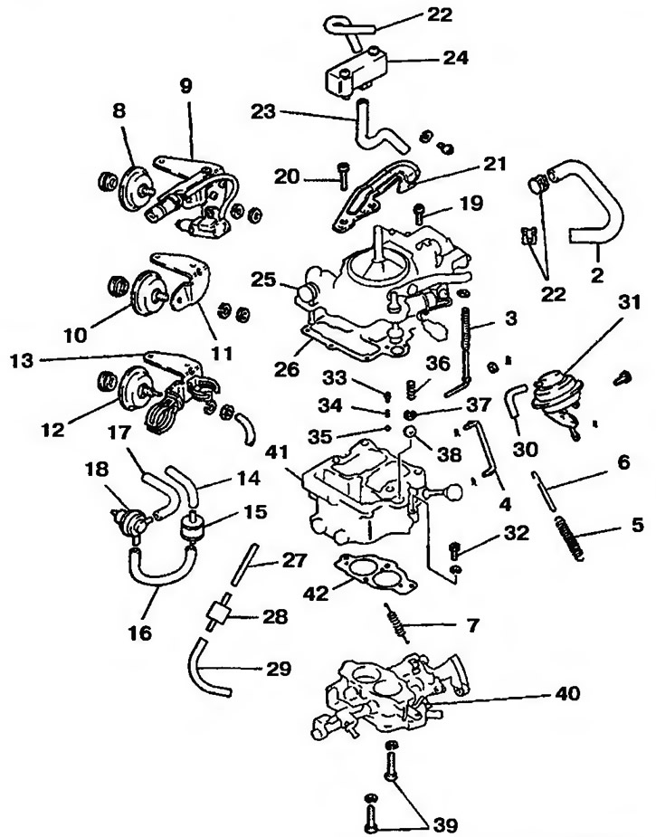
Pic. 10.7a. Carburetor type «A»: 1 - Clamp; 2 - Branch pipe of the cooling system; 3 - Pump rod; 4 - Throttle rod; 5 - Throttle valve return spring; 6 - Spring; 7 - Return spring; 8, 10, 12 - Throttle dampers; 9 - Throttle position sensor with bracket; 11, 13 - Brackets; 14, 16, 22, 23, 27, 29, 30 - Tubes; 15 - Retarding valve; 18 - Servo valve; 19, 20, 32, 39 - Bolts; 21 - Bracket; 24 - Idling compensator; 25 - Carburetor cover; 26 - Gasket; 28 - Vacuum retarding valve; 31 - diaphragm chamber; 33 - Pin; 34 - Spring; 35, 38 - Check valve balls; 36 - Damping spring of the pump; 37 - Retainer; 40 - Throttle body; 41 - Body of the float chamber; 42 - Gasket
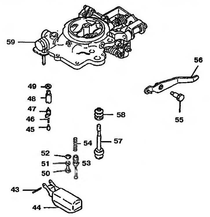
Pic. 10.7b. Carb cover: 43 - Axis of the float; 44 - float; 45 - Movable pin; 46 - Spring; 47 - Needle valve; 48 - Needle valve seat; 49 - Gasket; 50, 55 - Bolts; 51 - Washer; 52 - Limiter; 53 - Full load piston; 54 - Piston spring; 56 - Pump lever; 57 - Pump plunger; 58 - Corrugated cover; 59 - Carburetor cover
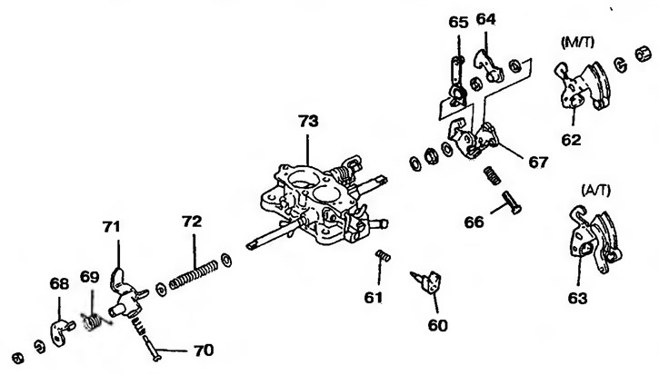
Pic. 10.7c. Carburetor throttle bodies: 60 - Adjusting bolt for the amount of combustible mixture; 61, 69, 72 - Springs; 62 - Throttle lever (manual transmission); 63 - Throttle lever (automatic transmission); 64 - Lever; 65 - Pusher; 66 - Adjusting bolt for idle speed; 67 - Earring; 68 - Lever A of the throttle closing damper; 70 - Adjusting bolt; 71 - Lever B of the throttle closing damper; 73 - Throttle body
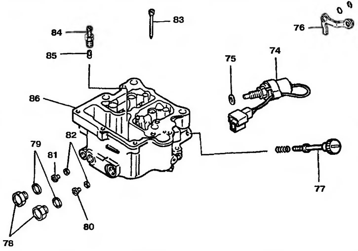
Pic. 10.7y. Carburetor float chamber: 74 - Electromagnetic shut-off valve; 75, 79, 82 - Gaskets; 76 - Lever; 77 - Speed adjusting bolt; 78 - Cork; 80 - Primary jet; 81 - Secondary jet; 83 - Idle jet; 84 - Full load valve; 85 - Full load jet; 86 - Float chamber
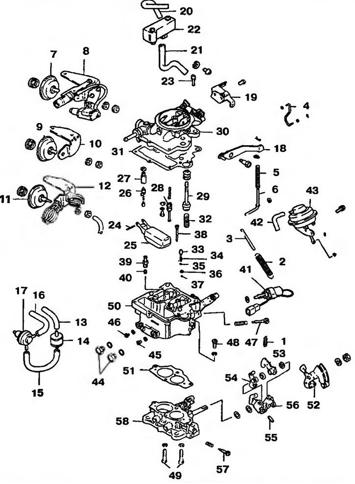
Pic. 10.8. Carburetor type «IN»: 1 - Secondary spring; 2 - Return spring; 3 - Damping spring; 4 - Throttle actuator rod; 5, 32, 34 - Springs; 6 - Connecting rod of the pump; 7, 9, 11 - dampers for closing the throttle; 8 - Bracket for throttle position transmitter; 10, 12, 19 - Brackets; 13, 15, 16, 20, 21 - Tubes; 14 - Deceleration valve; 17 - Servo valve; 18 - Pump lever; 22 - Idling compensatory valve; 23, 48, 49 - Bolts; 24 - Axis of the float; 25 - float; 26 - Needle valve; 27 - Needle valve seat; 28 - Full load piston; 29 - Pump plunger; 30 - Carburetor cover; 31, 51 - Gaskets; 33 - Weight; 35, 37 - Check valve balls; 36 - Retainer; 38 - Idle jet; 39 - Full load valve; 40 - Full load jet; 41 - Electromagnetic shut-off valve; 42 - Vacuum hose; 43 - Decompression chamber; 44 - Cork; 45 - Primary jet; 46 - Secondary jet; 47 - Speed adjusting bolt; 50 - Float chamber; 52 - Gas lever; 53, 56 - Levers; 54 - Idle speed adjustment lever; 55 - Adjusting bolt for idle speed; 57 - Adjusting bolt for the amount of combustible mixture; 58 - Throttle body
Disassembly
1. Using the special tool MD 998299, remove the idle speed limiter and the air mixture adjusting screw (pic. 10.9).
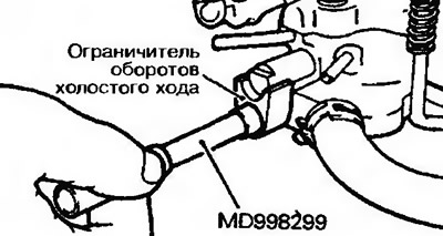
Pic. 10.9. Remove the idle speed limiter and air mixture adjustment screw
2. Remove the screw plug first, then insert a screwdriver into the threaded hole of the plug seat to unscrew the main jet (pic. 10.10).
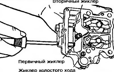
Pic. 10.10. Unscrewing the main jet
Examination
3. Check fuel and air passages for blockage. If they are clogged, wash the clogged parts with detergent or special cleaning liquid (nozzles, etc.) and blow with pressurized air (pic. 10.11). Do not use wire or metal objects for cleaning.
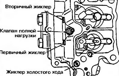
Fig.10.11. Checking the fuel and air channels of the carburetor
4. Check diaphragms, o-rings and springs for damage.
5. Pay attention to the smooth operation of the needle valve (pic. 10.12). If the valve is difficult to move or is stuck, it must be repaired or replaced.
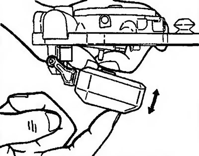
Fig.10.12. Needle valve operation test
6. Check intake fuel filter (located above the needle valve) for blockage and damage.
7. Check the operation of the float, deformation and damage to the lever and float.
8. Check throttles and traction system. If they are difficult to move, wash the parts and apply a light coat of engine oil to their rollers.
9. Check up absence of damages and cracks on a cover and the case of the carburetor.
Installation
10. If the main jet or idle jet is replaced, the new jet must be the same size as the old one, as they were originally sized to the exact dimensions due to capacity (each jet has its own number) (pic. 10.13).
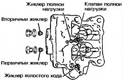
Figure 10.13. Installation of jets
11 Install the main jet and idle jet The primary jet is yellow brass, the secondary jet is white.
12 The primary and secondary jets and the idle jet have cuts of various sizes at the ends to simplify identification (rice 10 14).
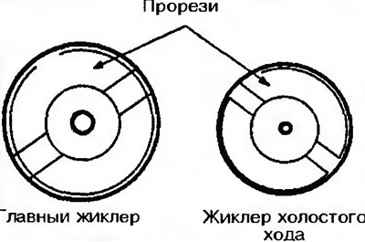
Pic. 10.14. Jet marking
Float height adjustment
13 Rotate the carburetor cap and remove the hook located on the needle valve (rice 10 15).
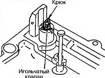
Pic. 10 15. Rotate the carburetor cap and remove the hook located on the needle valve
14. Install float and pin.
15. Press the float all the way up and measure the gap between the needle valve and the float arm (pic. 10.16). Target value: 15-17 mm.
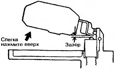
Pic. 10.16. Checking clearance between needle valve and float arm
| Lever position | Gap |
| bend over | is increasing |
| Straighten | Decreases |
16. If the value is not as specified, adjust it by bending the lever (pic. 10.17).
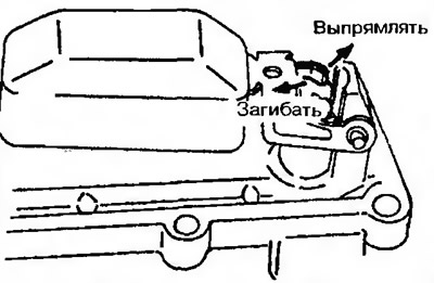
Figure 10.17. Gap adjustment between needle valve and float arm
17. Let the float sink under your own weight and then measure the distance between the float and the carb cap (pic. 10.18).
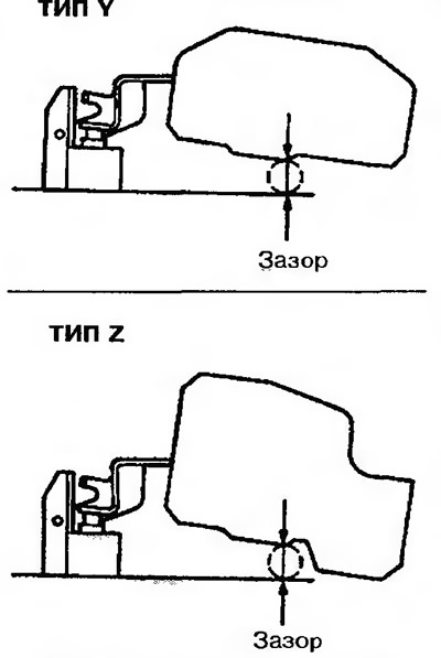
Pic. 10.18. Checking the distance between the float and the carburetor cover
Type Y - about 8.0 mm, type Z - about 7.4 mm.
18. If the distance does not correspond to the specified one, adjust it by tilting the workpiece (arrow) (pic. 10.19).
19. Remove the float and install the hook on the needle valve.
20. Install the float when the float knuckle hangs on the hook.
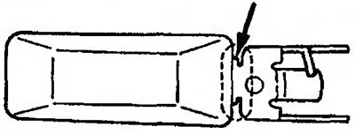
Pic. 10.19 Adjusting the distance between the float and the carburettor cap
Inspection and adjustment after assembly
21. Before checking and adjusting, the carburetor must be placed in a room with a temperature of less than 18°C for at least an hour and then in a room with a temperature of about 23°C for at least an hour (carburetor type «A»).
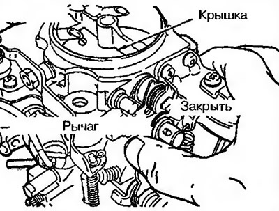
22. Please note that the alignment mark on the lever matches the center punch mark on the pusher (carburetor type «A») (pic. 10.20).

Pic. 10.20. Alignment of the marks on the lever with the punch mark on the pusher
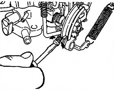
23. Move the choke lever until it closes completely (carburetor type «IN») (pic. 10.21).
Pic. 10.21. Checking the closing of the air damper
24. Measure the gap between the primary flap and the carburetor wall (pic. 10.22).
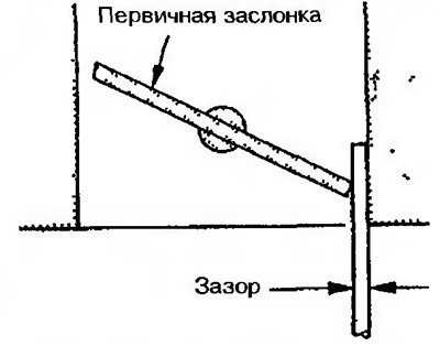
Pic. 10.22. Checking the gap between the primary damper and the wall
25. If the gap does not meet the allowable values, adjust it with the idle speed adjusting bolt (pic. 10.23).
Pic. 10.23. Adjustment of a backlash by an adjusting bolt of turns of idling
| Direction of rotation of the adjusting bolt | Gap | Remarks |
| Clockwise | is increasing | Idle speed increases |
| Counterclock-wise | Decreases | Idle speed decreases |
Checking the air damper
26. With the primary throttle fully open, move the secondary throttle lever with your finger to make sure that the secondary valve shaft does not have excessive play and the secondary valve moves freely.
27. If the secondary damper moves tight, clean the damper and adjacent surfaces, then lubricate the axle with engine oil.
28. If the secondary damper shaft has excessive clearance, replace the throttle body.
Channel check
29. When connecting a hand vacuum pump to individual channels, check them for blockage (pic. 10.24, a, b).
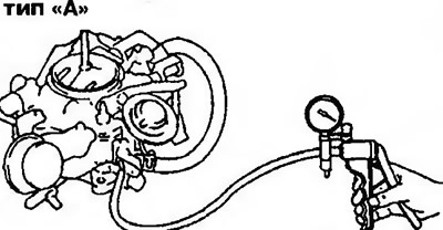
Pic. 10.24a. Checking for clogged carburetor passages | 
Pic. 10.24b. Checking for clogged carburetor passages |
30. If you find a blockage, clear the appropriate channel and blow out with air under pressure.