
English Русский
Български
Беларускі
Український
Српски
Hrvatski
Română
Polski
Slovenský
Magyar
Articles Bookmark Contacts Sitemap   
Company Audi Company Ford Company Hyundai Company Kia Company Mazda Company Mercedes-Benz Company Nissan
MitsubishiMan.ru


Home Colt Lancer Galant L200 Outlander Pajero Others
Lancer 9 (2000-2007, petrol) Lancer 3 and 5 (1984-1992)

Checking/adjusting the closing angle (Mitsubishi Lancer 3)

  • Home
  • Lancer
  • 3 (1984-1992)
  • Power unit
  • Ignition system
  • Checking/adjusting the closing angle
0
Contents: Checking with a special device for…⤓ Adjustment using a special device…⤓ Adjustment using a set of feeler…⤓
To accurately set the angle of the breaker contacts, a special device for measuring the angle of the closing is used at service stations. This device has the advantage of allowing accurate setting of the closing angle even with slightly burnt contact surfaces. When using a special measuring device, connect it according to the manufacturer's instructions. However, as a temporary measure, instead of setting the closing angle, the contact gap can be adjusted.

Checking with a special device for measuring the closing angle


Connect the measuring device in accordance with the manufacturer's operating instructions.

Turn the engine over with the starter or run it at idle speed. Take the instrument reading.

The value of the closing angle should be 52° ±6° degrees. If the measured value is out of tolerance, adjust the closing angle.

Adjustment using a special device for measuring the closing angle


Using a screwdriver, release the 2 retaining clips on the side of the ignition distributor and remove the distributor cover.

Place the distributor cap aside so that any spark that may occur is reliably diverted to ground and cannot come into contact with your body.

Loosen, without unscrewing, the fastening screw "2" (Fig. G-1205).

Set the gearbox to neutral, set the handbrake. Have the assistant turn the engine with the starter and set the desired closing angle by shifting the contact pad of the breaker.


If the closing angle is too small, the distance between the distributor cam and the hammer should be reduced; if the angle is too large, the distance should be increased.

After setting the required angle value, tighten the fastening screws and check the closing angle again. If it goes beyond the tolerance, repeat the adjustment.

Adjustment using a set of feeler gauges


If there is no special measuring device, as a temporary measure, the setting of the closing angle can be made using a set of feeler gauges. Subsequently, it will be necessary to check the value of the closing angle using a special measuring device and possibly make adjustments.

Remove the spark plug distributor cap and remove the distributor rotor.

Engage 4th gear and move the car on a level surface or turn the engine by the crankshaft pulley until the plastic slider of the breaker contact is adjacent to the highest point of the distributor cam. When the gap is set correctly, the feeler gauge should fit tightly between the contact surfaces. The gap should be 0.45-0.55 mm, otherwise it should be adjusted.
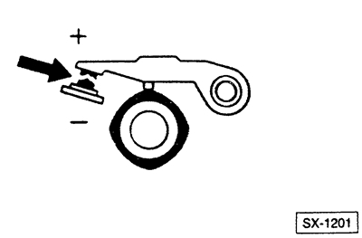


In this case, when adjusting, you should strive for the lowest permissible value.


Attention: If the contacts are burnt, measure the gap only along the edge - in the middle, the measurements are distorted due to the presence of bumps on the surface of the contacts.


If the gap size does not correspond to the permissible values: Slightly loosen screws "1" and "2" (do not unscrew), see Fig. G-1205. Slightly move the contact support pad of the breaker with a screwdriver until the feeler gauge fits tightly between the contact surfaces.

After setting the required value, tighten the mounting screws.

Note: Since the installation using the feeler gauge is not precise, the closing angle must be checked later using a special measuring device.


Place the distributor boot and distributor runner onto the distributor axle, with the runner protrusion fitting into the recess on the axle.

Place the distributor cap on and install both retaining clips.

Set the ignition timing.
This article is available at: russian, bulgarian, belarusian, ukrainian, serbian, croatian, romanian, polish, slovak, hungarian
This article was reviewed by: Dmitry Vasiliev
Share with friends:
◀ Previous
Lancer 3 and 5: Ignition system
Next ▶

Replacing breaker contacts
Checking the ignition wires
Checking the ignition coil
Ignition distributor — device
Precautions when working with the ignition system
Checking/setting ignition timing
Removal and installation the ignition distributor
Spark plugs — general information
Recommended spark plug parameters for COLT / LANCER
Ignition timing table
Similar materials for other Mitsubishi models

➤ Checking and adjusting the ignition timing angle Mitsubishi Colt 2 and 3 (1983-1993)
➤ Checking the condition, adjusting the tension force and… Mitsubishi Galant 6 and 7 (1987-1998)
➤ Adjusting the steering column angle Mitsubishi L200 4 (2005-2014, diesel)
➤ Checking free play and checking the steering wheel angle Mitsubishi Outlander 1 (2003-2008)
➤ Drive Belts — Checking and Adjusting Tension Mitsubishi Pajero 1 and 2 (1982-1999)
➤ Checking and adjusting the tension of the generator drive… Mitsubishi Carisma (1995-2004)
Link in different formats to this article
Comments and feedback from visitors
No comments yet


Add up two numbers 11 + 17


Lancer 9 (2000-2007, petrol) 
  • General information
  • User manual
  • Maintenance
  • Power unit
  • Repair of MPI engines
  • Repair of GDI engines
  • Engine overhaul
  • Cooling and lubrication system
  • MPI fuel injection system
  • GDI fuel injection system
  • Intake and exhaust system
  • Starting and charging system
  • Transmission
  • Automatic gearbox
  • Variator (CVT)
  • Drive shafts and gearbox
  • Chassis and running gear
  • Front suspension
  • Rear suspension
  • Steering
  • Brake system
  • Body and interior
  • Doors, locks and windows
  • Exterior (external elements)
  • Interior (internal elements)
  • Electrical equipment
  • Heater and air conditioner
  • Security system SRS
  • Equipment and devices
  • Wiring diagrams (saloon)
  • Wiring diagrams (wagon)
Lancer 3 and 5 (1984-1992) 
  • General information
  • Maintenance
  • Power unit
  • Engine repair
  • Lubrication system
  • Cooling system
  • Ignition system
  • Fuel system
  • Carburetor
  • Fuel injection
  • Diesel power system
  • Exhaust system
  • Transmission
  • Clutch
  • Car gearbox
  • Chassis and running gear
  • Front suspension
  • Rear suspension
  • Steering
  • Brake system
  • Wheels and tires
  • Body and interior
  • Exterior (external elements)
  • Interior (internal elements)
  • Heating system
  • Electrical equipment
  • Equipment and devices
  • Power devices
  • Electrical circuits
MitsubishiMan.ru © 2018–2026 • Mobile version • Articles about Mitsubishi • Contacts • Sitemap: EN BG BY UA RS HR RO PL SK HU • Site search • Bookmark
Colt 2 and 3 (1983-1993) · Colt 4 and 5 (1991-2003) · Colt 5 (1995-2003) · Lancer 3 and 5 (1984-1992) · Lancer 9 (2000-2007) · Galant 5 (1983-1989) · Galant 6 and 7 (1987-1998) · L200 4 (2005-2014) · Outlander 1 (2003-2008) · Pajero 1 and 2 (1982-1999) · Pajero 4 (2006-2021) · Carisma (1995-2004) · Space Star (1998-2005) ·
This resource sets cookies 🍪 to avoid bothering you with repeated data entry.