
English Русский
Български
Беларускі
Український
Српски
Hrvatski
Română
Polski
Slovenský
Magyar
Articles Bookmark Contacts Sitemap   
Company Audi Company Ford Company Hyundai Company Kia Company Mazda Company Mercedes-Benz Company Nissan
MitsubishiMan.ru


Home Colt Lancer Galant L200 Outlander Pajero Others
Pajero 4 (2006-2021) Pajero 1 and 2 (1982-1999)

Methods of working with measuring instruments — micrometers (Mitsubishi Pajero 4)

  • Home
  • Pajero
  • 4 (2006-2021)
  • General information
  • Maintenance
  • Methods of working with measuring instruments — micrometers
0


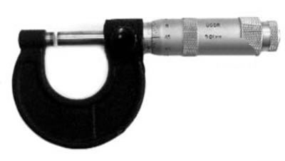
A micrometer is a device designed for measuring linear dimensions using the absolute contact method in the area of small dimensions with high accuracy (from 0.01 to 0.001 mm), the conversion mechanism of which is a screw-nut micropair.

It is necessary to keep the micrometer clean. Be careful not to drop the micrometer as the clamp may become deformed, resulting in inaccurate measurements.

The operation of the micrometer is based on the movement of the screw along the axis when it rotates in a fixed nut. The displacement is proportional to the angle of rotation of the screw around the axis. Full revolutions are counted on a scale printed on the stem of the micrometer, and fractions of a revolution are counted on a circular scale printed on the drum. The optimal movement of the screw in the nut is only a length of no more than 25 mm due to the difficulty of producing a screw with an accurate pitch over a greater length. Therefore, the micrometer is manufactured in several standard sizes for measuring lengths from 0 to 25 mm, from 25 to 50 mm, etc. For micrometers with measurement limits from 0 to 25 mm, with the closed measuring planes of the heel and the micrometer screw, the zero mark of the drum scale must exactly coincide with the longitudinal mark on the stem, and the beveled edge of the drum - with the zero mark of the stem scale. For measurements of lengths greater than 25 mm, a micrometer with replaceable anvils is used; setting such micrometers to zero is done using a setting measure applied to the micrometer or end measures. The product being measured is clamped between the measuring planes of the micrometer. Usually the pitch of the screw is 0.5 or 1 mm and accordingly the scale on the stem has a division value of 0.5 or 1 mm, and 50 or 100 divisions are applied to the drum to obtain a reading of 0.01 mm. This reading value is the most common, but there are micrometers with a reading of 0.005, 0.002 and 0.001 mm. Constant axial force when the screw contacts the part is provided by a friction device - a ratchet. When the measuring surfaces of the micrometer tightly contact the surface of the measured part, the ratchet begins to turn with a slight crack, and the rotation of the microscrew should stop after three clicks.
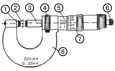


1. Heel.; 2. Subject of measurement.; 3. Spindle.; 4. Wheel.; 5. Measuring scale (in mm).; 6. Ratchet.; 7. Drum vernier.; 8. Bracket.


When taking measurements, the object (2) is clamped between the heel and the micrometer screw (3). On the surface of the stem there are two line scales, offset relative to each other by 0.5 mm, and having a division value of 1 mm. The drum (7) rotates around the circular scale, which is also located on the bevel of the drum. The micrometer screw can be fixed in any position. The screw is equipped with a ratchet mechanism to ensure constant measuring pressure.

1. The object is placed between the heel and the micrometer screw, while rotating the drum, the spindle is set to an approximately close size of the object.

2. The spindle is carefully moved until it comes into contact with the object being measured.

3. The size in mm is determined using the drum vernier, which corresponds to the horizontal index line of the stem scale.

4. The overall size of the measured object is determined.

Note: When in contact with the measured object, do not tighten the spindle by rotating the drum sleeve by hand, this may cause the micrometer to break. To determine the dimensions more accurately, it is necessary to make sure that the item is well secured.
This article is available at: russian, bulgarian, belarusian, ukrainian, serbian, croatian, romanian, polish, slovak, hungarian
This article was reviewed by: Miroslav Rakov
Share with friends:
◀ Previous
Pajero 4: Maintenance
Next ▶

Methods of working with measuring instruments — flat probes
Basic set of necessary tools
Environmental protection
Precautions when working with Supplemental Restraint System (SRS) components
Precautions when working with toxic substances and materials
Methods of working with measuring instruments — calipers
Dial type indicator
Methods of working with measuring instruments — bore gauge
Similar materials for other Mitsubishi models

➤ Measuring instruments and indicators Mitsubishi Colt 5 (1995-2003, petrol)
➤ Precautions when working with the ignition system Mitsubishi Lancer 3 and 5 (1984-1992)
➤ Checking the fuel pump, measuring the fuel pressure Mitsubishi Galant 6 and 7 (1987-1998)
➤ Disassembly and assembly of the fuel tank measuring and… Mitsubishi L200 4 (2005-2014, diesel)
➤ Checking the level of working fluid in the clutch hydraulic… Mitsubishi Outlander 1 (2003-2008)
➤ Control and measuring instruments and controls Mitsubishi Carisma (1995-2004)
Link in different formats to this article
Comments and feedback from visitors
No comments yet


Add up two numbers 17 + 22


Pajero 4 (2006-2021) 
  • General information
  • User manual
  • Troubleshooting
  • Maintenance
  • Technical specifications
  • Power unit
  • Engine repair
  • Cooling system
  • Lubrication system
  • Fuel system
  • Engine management system
  • Intake and exhaust system
  • Engine electrical equipment
  • Transmission
  • Clutch
  • Manual gearbox
  • Automatic gearbox
  • Drive shafts
  • Chassis and running gear
  • Front suspension
  • Rear suspension
  • Brake system
  • Steering
  • Body and interior
  • Exterior (external elements)
  • Interior (internal elements)
  • Doors, locks and windows
  • Body dimensions
  • Electrical equipment
  • Safety system (SRS)
  • Air conditioner
  • Equipment and devices
  • Electrical diagrams
Pajero 1 and 2 (1982-1999) 
  • General information
  • User manual
  • Seats and seat belts
  • Instruments and controls
  • Driving and operation
  • Maintenance
  • Power unit
  • Gasoline engines
  • Diesel engines
  • Ignition system
  • Engine electrical equipment
  • Cooling and lubrication system
  • Power and exhaust system
  • Fuel system (gasoline)
  • Fuel system (diesel)
  • Transmission
  • Clutch
  • Mechanical gearbox
  • Automatic gearbox
  • Drive shafts and axles
  • Chassis and running gear
  • Front suspension
  • Rear suspension
  • Steering
  • Brake system
  • Body and interior
  • Exterior (external elements)
  • Interior (internal elements)
  • Doors, locks and windows
  • Electrical equipment
  • Equipment and devices
  • Heater and air conditioner
  • Cruise control
  • Headlights and lighting
  • Electrical circuits
MitsubishiMan.ru © 2018–2026 • Mobile version • Articles about Mitsubishi • Contacts • Sitemap: EN BG BY UA RS HR RO PL SK HU • Site search • Bookmark
Colt 2 and 3 (1983-1993) · Colt 4 and 5 (1991-2003) · Colt 5 (1995-2003) · Lancer 3 and 5 (1984-1992) · Lancer 9 (2000-2007) · Galant 5 (1983-1989) · Galant 6 and 7 (1987-1998) · L200 4 (2005-2014) · Outlander 1 (2003-2008) · Pajero 1 and 2 (1982-1999) · Pajero 4 (2006-2021) · Carisma (1995-2004) · Space Star (1998-2005) ·
This resource sets cookies 🍪 to avoid bothering you with repeated data entry.