



Electronic immobilizer control unit
Removal
To remove, follow these steps.
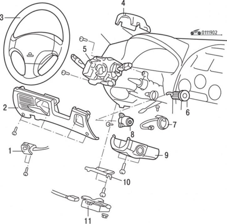
Fig. 19.2. Ignition switch and immobilizer: 1 – hood lock drive handle; 2 – lower panel on the driver"s side; 3 – steering wheel; 4 – Upper steering column cover; 5 – combined steering column switch; 6 – steering column lock; 7 – ignition switch ring antenna; 8 – ignition switch; 9 – lower steering column cover; 10 – bracket; 11 – electronic immobilizer control unit
1. Loosen the screws and remove the drive handle 1 (Fig. 19.2) of the hood lock.
2. Loosen the screws and remove the lower panel 2 from the driver's side.
3. Loosen the bolts and remove bracket 10.
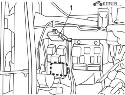
Fig. 19.3. Location of the electronic unit (1) for immobilizer control
4. Loosen the nuts, disconnect the electrical connector and remove the immobilizer electronic control unit (Fig. 19.3).
Installation
Installation is carried out in the reverse order of removal.
Ignition switch and ignition switch ring antenna
Removal
To remove, follow these steps.
1. Loosen the screws and remove handle 1 (see Fig. 19.2) of the hood lock drive.
2. Remove the screws and lower panel 2 from the driver's side.
3. Remove the steering wheel 3.
4. Remove the screws and remove the upper 4 and lower 9 steering column covers.
5. Remove the combination steering column switch.
6. Disconnect the electrical connector and remove the ring antenna 7 of the ignition switch.
7. Remove the steering column lock.
8. Insert the key into the ignition switch and turn it to the "ACC" position.
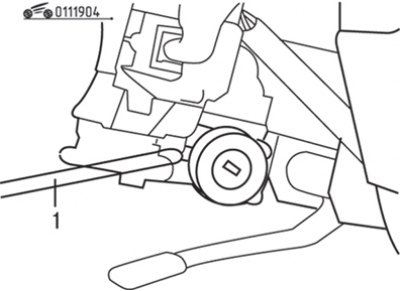
Fig. 19.4. Using a screwdriver (1) to remove the ignition switch cylinder
9. Using a thin Phillips-head screwdriver, push the cylinder locking pin inward and then pull it out towards you (Fig. 19.4).
Examination
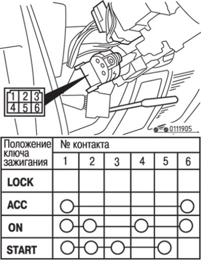
Fig. 19.5. Electrical connector of the ignition switch and contact positions at different key positions
1. Disconnect the connector from the ignition switch (Fig. 19.5).
2. Turn the ignition key to different positions to check the electrical circuits of the ignition switch.
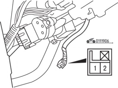
Fig. 19.6. Location of contacts on the ignition switch ring antenna connector
3. Using a tester, check the electrical circuit between the contacts of the ignition switch ring antenna connector (Fig. 19.6). The circuit should be closed.
Installation
Installation is carried out in the reverse order of removal.
[The original article is on: www.mitsubishiman.ru]