



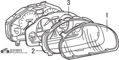
Fig. 19.11. Removing the glass (1), rim (2) and plate (3) of the instrument cluster
1. Remove the glass, bezel and instrument cluster plate (Fig. 19.11).
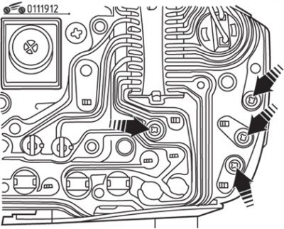
Fig. 19.12. Location of fuel level indicator mounting screws
2. Loosen the fuel gauge mounting screws and remove the fuel gauge from the instrument cluster housing (Fig. 19.12).
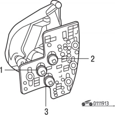
Fig. 19.13. Location of fuel level indicator terminals: 1 – fuel level indicator; 2 – nutrition; 3 - "mass"
3. Using a tester, measure the resistance between the following terminals shown in Fig. 19.13.
Nominal resistance, Ohm:
- nutrition - "mass" - 122-153;
- power supply – fuel gauge – 27–35;
- fuel level indicator – "mass" – 95–119.