



Retractable antenna
Removal
To remove the antenna, follow these steps.
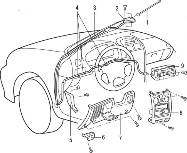
Fig. 19.49. Retractable antenna: 1 – antenna pin; 2 – antenna base; 3 – assembled antenna; 4 – clamps; 5 – lower trim of the front pillar; 6 – hood lock drive handle; 7 – lower panel on the driver"s side; 8 – center console panel; 9 – radio
1. Unscrew and remove pin 1 (Fig. 19.49) of the antenna.
2. Loosen the screws and remove the center console panel.
3. Remove the radio 9.
4. Loosen the screws and remove the 6 hood lock drive handle.
5. Remove the lower panel from the driver's side.
6. Release the feeder from the clamps 4.
7. Remove the lower trim of the 5th front pillar.
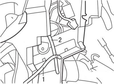
Fig. 19.50. Fastening the cord (1) to the antenna feeder (2)
8. Tie the cord to the end of the feeder (Fig. 19.50).
9. Loosen the screws and remove the antenna base.
10. Pull out the antenna base until the end of the drain tube is visible.
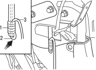
Fig. 19.51. Securing the cord with insulating tape: 1 – insulating tape; 2 – hole; 3 – cord
11. Thread the cord through the hole at the end of the drain tube and tie it with insulating tape (Fig. 19.51).
Caution: Tie the cord tightly with tape so that it does not slip out.
12. Gradually pull out the antenna base and remove it.
Installation
Installation is carried out in the reverse order of removal.
Electrically powered antenna
Caution: When removing and installing the floor console assembly on vehicles equipped with the SRS system, do not allow it to impact the SRS electronic control unit or other system components.
Removal
To remove the electric antenna, follow these steps:.
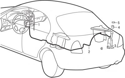
Fig. 19.52. Antenna with electric drive: 1 – radio; 2 – antenna feeder; 3 – assembled electric driven antenna; 4 – base; 5 – round nut
1. Remove radio 1 (Fig. 19.52).
2. Remove the front and rear floor console.
3. Remove the right front seat assembly.
4. Remove the rear seat cushion and right side backrest assembly.
5. Remove the right front pillar trim, right front and right rear protective pads, right center pillar lower trim and right rear pillar trim.
6. Remove the speaker mounting bracket.
7. Remove antenna feeder 2.
8. Remove the rear right side trim.
9. Unscrew the round nut 5.
10. Remove the base.
11. Loosen the nuts and remove the antenna with electric drive assembly.
Examination
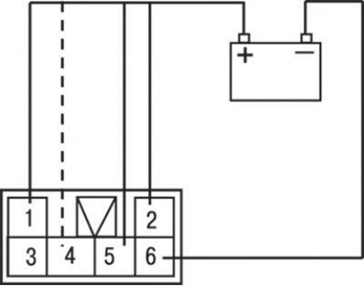
Fig. 19.53. Electrical circuit for testing an antenna with an electric drive
Draw an electric circuit as shown in Fig. 19.53 (solid lines).
1. Check that the antenna extends when the connection indicated by the dotted line is closed.
2. Check that the antenna retracts when the connection indicated by the dotted line is broken.
Replacing the retractable antenna
1. Unscrew the round nut.
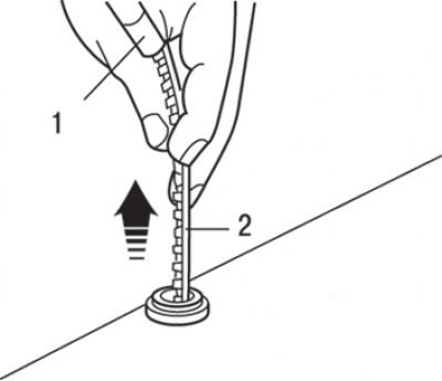
Fig. 19.54. Removing the telescopic part of the antenna: 1 – telescopic part of the antenna; 2 – toothed cable
2. After turning the ignition key to the "ACC" or "ON" position, turn the radio switch to the "ON" position to raise the retractable antenna and remove it together with the toothed cable (Fig. 19.54).
3. Extend the retractable antenna to its maximum length.
Caution: If the toothed cable is bent in the area of the electric drive, correct the bend.
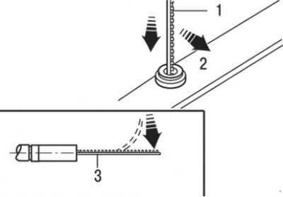
Fig. 19.55. Installing the cable with the toothed part facing the luggage compartment: 1 – toothed part of the cable; 2 – luggage compartment side; 3 – Elimination of toothed cable bending
4. Insert the toothed cable into the electric drive so that the toothed part of the cable is directed towards the luggage compartment (Fig. 19.55).
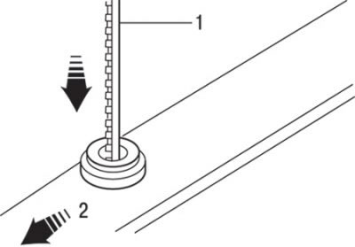
Fig. 19.56. Subsequent rotation of the toothed part of the cable towards the rear of the vehicle: 1 – toothed part of the cable; 2 – rear of the car
5. Turn the teeth of the toothed cable towards the rear of the vehicle (exactly 90°) so that the toothed cable engages with the electric drive gear (Fig. 19.56).
6. If the toothed cable is pulled out without resistance when lightly pulled, it is not engaged with the electric drive gear. In this case, check the cable for bends at the end and reinstall it.
7. Position the retractable antenna vertically and turn the radio switch to the "OFF" position to retract the toothed cable. Insert the retractable antenna from its motor side to align it with the wound toothed cable.
8. After tightening the round nut, check the antenna movement by turning the radio on and off.