English Русский
Български
Беларускі
Український
Српски
Hrvatski
Română
Polski
Slovenský
Magyar
Articles Bookmark Contacts Sitemap   
Company Audi Company Ford Company Hyundai Company Kia Company Mazda Company Mercedes-Benz Company Nissan
MitsubishiMan.ru


Home Colt Lancer Galant L200 Outlander Pajero Others
Pajero 4 (2006-2021) Pajero 1 and 2 (1982-1999)

Front and rear oil seals — removal and installation (Mitsubishi Pajero 1)

  • Home
  • Pajero
  • 1 (1982-1999)
  • Transmission
  • Drive shafts and axles
  • Front and rear oil seals — removal and installation
0
Contents: Disassembly and assembly ⤓ Removal and installation ⤓

Disassembly and assembly


1. Disconnect the battery from ground.

2. Raise the car.

3. Drain the oil from the transfer case.

4. Mark the position of the cardan shaft flanges, unscrew the nuts, disconnect the flange and remove the shaft from the transmission (or transfer case).

5. Remove the dust cover, pry up and pull out the oil seal.

6. Assembly is carried out in reverse order.

7. Press the new seal in with a mandrel (mIT3995 and MB990938-01 tools) until the plane of the seal is aligned with the gearbox housing (transfer case).

8. When assembling, align the marks on the cardan shafts that were applied during disassembly.

Removal and installation


1. Disconnect the battery from ground.

2. Remove the transmission assembly with the transfer case.

3. Remove the filling pipe and unscrew the plugs.

4. Remove the retainer spring and plunger (or ball).

5. Remove the spring loaded pin from the transmission shift slider.

6. Loosen the nuts/bolts and remove the transfer case.

7. Note the position of the 2 wire retainers on the transfer case mounting bolts.

8. When separating the crankcases, remove the transfer case lever.

9. Installation is carried out in reverse order.

10. Replace the gasket and install it with 3M ART N 8001 or N 8011 sealant, lubricating both sides. Lubricate the transmission secondary shaft to make it easier to install into the transfer case.

11. Tighten all connections to the required torques.


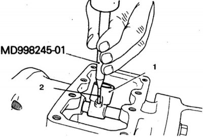
12. Press the spring-loaded pin (2) into the slider (1) of the transfer case using the MD998245-01 tool (allowed with a beard).


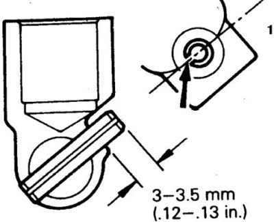
13. The pin groove must be oriented in a certain direction when pressing in (keep the size at 3–3.5 mm) (1 – axis of symmetry of the transfer case control shaft).
This article is available at: russian, bulgarian, belarusian, ukrainian, serbian, croatian, romanian, polish, slovak, hungarian
This article was reviewed by: Arseny Pavlov
Share with friends:
◀ Previous
Pajero 1 and 2: Drive shafts and axles
Next ▶

Transfer case — design description
Front propeller shaft and crosspieces — removal and installation
Replacing the front universal joint
Rear propeller shaft and crosspieces — removal and installation
Replacing the rear cardan joint
Front Drive Axle Design
Similar materials for other Mitsubishi models

➤ Brake pads for disc brakes (front and rear) — replacement Mitsubishi Colt 2 and 3 (1983-1993)
➤ Front side lights, rear side lights, number plate lights… Mitsubishi Lancer 9 (2000-2007, petrol)
➤ Disc brake pads (front and rear) — replacement Mitsubishi Galant 5 (1983-1989, petrol)
➤ Inspection of front and rear suspension components Mitsubishi L200 4 (2005-2014, diesel)
➤ Removal and installation front and rear crankshaft oil… Mitsubishi Outlander 1 (2003-2008)
➤ Front seat adjustment Mitsubishi Carisma (1995-2004)
Link in different formats to this article
Comments and feedback from visitors
No comments yet


Add up two numbers 48 + 30


Pajero 4 (2006-2021) 
  • General information
  • User manual
  • Troubleshooting
  • Maintenance
  • Technical specifications
  • Power unit
  • Engine repair
  • Cooling system
  • Lubrication system
  • Fuel system
  • Engine management system
  • Intake and exhaust system
  • Engine electrical equipment
  • Transmission
  • Clutch
  • Manual gearbox
  • Automatic gearbox
  • Drive shafts
  • Chassis and running gear
  • Front suspension
  • Rear suspension
  • Brake system
  • Steering
  • Body and interior
  • Exterior (external elements)
  • Interior (internal elements)
  • Doors, locks and windows
  • Body dimensions
  • Electrical equipment
  • Safety system (SRS)
  • Air conditioner
  • Equipment and devices
  • Electrical diagrams
Pajero 1 and 2 (1982-1999) 
  • General information
  • User manual
  • Seats and seat belts
  • Instruments and controls
  • Driving and operation
  • Maintenance
  • Power unit
  • Gasoline engines
  • Diesel engines
  • Ignition system
  • Engine electrical equipment
  • Cooling and lubrication system
  • Power and exhaust system
  • Fuel system (gasoline)
  • Fuel system (diesel)
  • Transmission
  • Clutch
  • Mechanical gearbox
  • Automatic gearbox
  • Drive shafts and axles
  • Chassis and running gear
  • Front suspension
  • Rear suspension
  • Steering
  • Brake system
  • Body and interior
  • Exterior (external elements)
  • Interior (internal elements)
  • Doors, locks and windows
  • Electrical equipment
  • Equipment and devices
  • Heater and air conditioner
  • Cruise control
  • Headlights and lighting
  • Electrical circuits
MitsubishiMan.ru © 2018–2026 • Mobile version • Articles about Mitsubishi • Contacts • Sitemap: EN BG BY UA RS HR RO PL SK HU • Site search • Bookmark
Colt 2 and 3 (1983-1993) · Colt 4 and 5 (1991-2003) · Colt 5 (1995-2003) · Lancer 3 and 5 (1984-1992) · Lancer 9 (2000-2007) · Galant 5 (1983-1989) · Galant 6 and 7 (1987-1998) · L200 4 (2005-2014) · Outlander 1 (2003-2008) · Pajero 1 and 2 (1982-1999) · Pajero 4 (2006-2021) · Carisma (1995-2004) · Space Star (1998-2005) ·
This resource sets cookies 🍪 to avoid bothering you with repeated data entry.