



Caution: When removing and installing the floor console assembly for vehicles equipped with the SRS system, do not allow impact to the SRS control unit or other system components.
Central console of cars produced since 1995
Removal
To remove the floor console, follow these steps:.
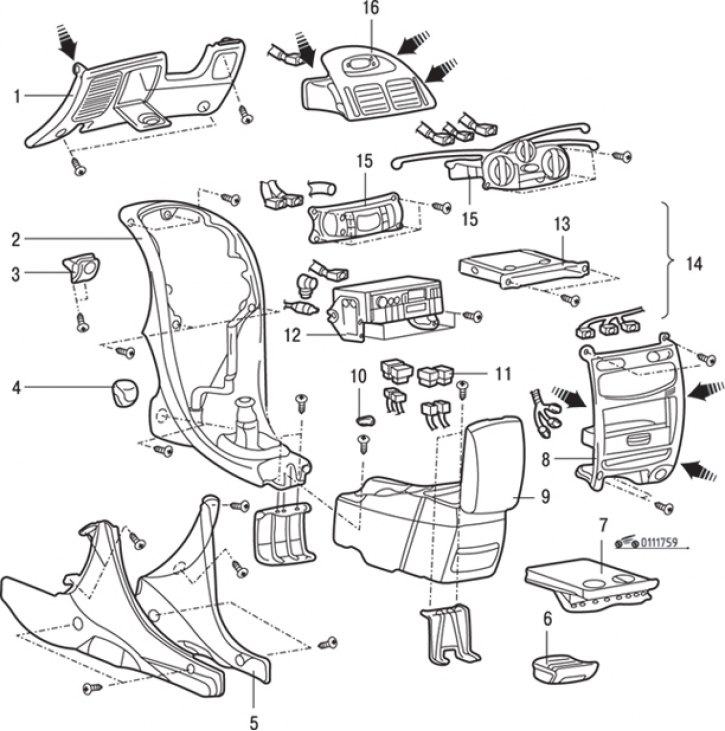
Fig. 17.59. Central console of cars produced since 1995: 1 – lower cover of the instrument panel; 2 – front floor console assembly; 3 – hood lock release handle; 4 – gear shift lever handle (manual transmission); 5 – console side covers; 6 – ashtray; 7 – internal cup holder; 8 – center console panel; 9 – rear floor console assembly; 10 – decorative console plug; 11 – switch; 12 – radio; 13 – external cup holder; 14 – center console and cup holder assembly; 15 – heater control panel assembly; 16 – central air supply deflector into the passenger compartment
1. Unscrew the two screws and remove the handle 3 (Fig. 17.59) of the hood lock drive.
2. Loosen the three screws, release the mounting brackets and remove the lower cover 1 of the instrument panel.
3. Unscrew four screws and remove the side covers 5 of the console.
4. Using a screwdriver blade as a lever, release the fastening brackets and remove the central air intake deflector 16.
5. Remove the ashtray 6.
6. After unscrewing the screws securing the center console, pull the center console panel towards you together with the inner cup holder.
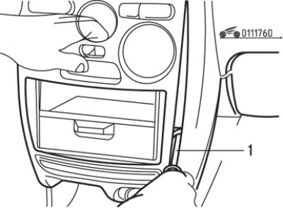
Fig. 17.60. Using a screwdriver (1) to remove the center console and cup holder
7. Insert a screwdriver into the gap as shown in Fig. 17.60 to remove the center console panel and cup holder assembly.
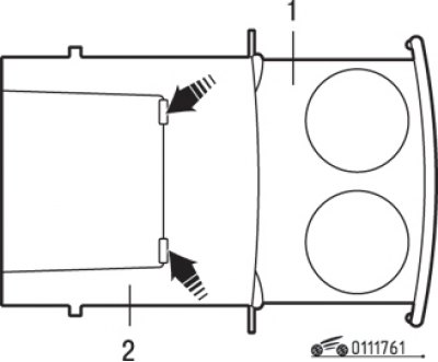
Fig. 17.61. Removing the inner cup holder: 1 – internal cup holder; 2 – external cup holder
8. Press the points on the outer cup holder shown by the arrows in Fig. 17.61 and remove the inner cup holder.
9. Unscrew the two screws and remove the outer cup holder 13 (see Fig. 17.59).
10. Loosen the screws and remove the heater control panel 15 as an assembly. Mark and disconnect the heater control cables from the panel.
11. Loosen the screws and remove the radio. 12. Disconnect the electrical connectors from the radio.
12. Using a screwdriver blade as a lever, remove the decorative caps 10 from the console.
13. Using a screwdriver blade as a lever, remove switches 11 and disconnect the connectors from them.
14. Loosen the screws and remove the rear floor console 9 as an assembly.
15. Pull up and remove the gear shift lever handle 4 (manual transmission).
16. Loosen the screws and remove the front floor console 2 assembly.
Installation
Installation is carried out in the reverse order of removal, taking into account the following.
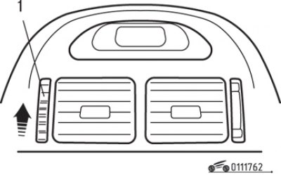
Fig. 17.62. Moving the handle (1) for supplying cold air from the central deflector into the passenger compartment
1. Move the cold air supply handle (central air supply grille into the passenger compartment) all the way up, as shown in Fig. 17.62.
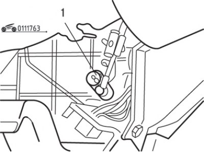
Fig. 17.63. Installing the drive cable (1) of the cold air supply flap
2. Turn the cold air supply flap drive on the heater side all the way down and install the cold air bypass flap drive cable (Fig. 17.63).
Central console of cars produced since 1999
Removal
To remove the floor console, follow these steps:.
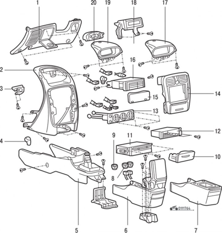
Fig. 17.64. Central console of cars since 1999: 1 – lower cover of the instrument panel; 2 – center console assembly; 3 – hood lock drive handle; 4 – gear shift lever handle (manual transmission); 5 – front floor console assembly; 6 – rear floor console assembly (with central armrest); 7 – rear floor console assembly (without central armrest); 8 – switch; 9 – flat plug; 10 – ashtray; 11 – navigation block; 12 – box; 13 – heater control panel; 14 – central panel assembly; 15 – radio plug; 16 – radio; 17 – display visor; 18 – display unit; 19 – display visor (clock); 20 – hours
1. Unscrew the two screws and remove the hood lock drive handle 3 (Fig. 17.64).
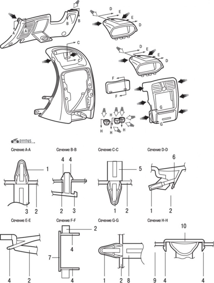
Fig. 17.65. Locations of fasteners (a) and latches (b) for securing the center console elements on vehicles manufactured since 1999: 1 – retainer; 2 – instrument panel; 3 – lower cover of the instrument panel; 4 – latch; 5 – center console; 6 – display visor; 7 – radio plug; 8 – central panel assembly; 9 – floor console; 10 – plug or switch
2. Unscrew the three screws, release the fasteners and latches (Fig. 17.65) and remove the lower cover 1 (see Fig. 17.64) of the instrument panel.
3. Using a screwdriver blade as a lever, release the clips and remove the center panel 14 as an assembly.
4. Remove ashtray 10.
5. Loosen the screws, release the clips and remove the display visor (display) 17. If the clock is installed in the display visor, disconnect the electrical connectors from it.
6. Loosen the screws, remove the display unit 18 and disconnect the electrical connectors from it.
7. Loosen the screws and remove the radio 16. Disconnect the electrical connectors from the radio.
8. If there is no radio, use a screwdriver blade as a lever to release the latches and remove the plug 15 (see Fig. 17.64), 7 (see Fig. 17.65) of the radio.
9. Loosen the screws and remove the heater control panel assembly 13. Mark and disconnect the heater control cables from the panel.
10. Loosen the screws and remove the navigation unit 11.
11. Remove box 12.
12. Using a screwdriver blade as a lever, remove switches 8 and disconnect the connectors from them.
13. Remove the flat plug 9.
14. Remove the screws and remove the rear floor console assembly 6 or 17 (with or without center armrest).
15. Pull up and remove the gearshift lever handle 4 (manual transmission).
16. Loosen the screws and remove the front floor console 5 assembly.
17. Loosen the screws and remove the center console 2 as an assembly.
Installation
Installation is carried out in the reverse order of removal.