



Contents: Removal ⤓ Installation ⤓
Removal
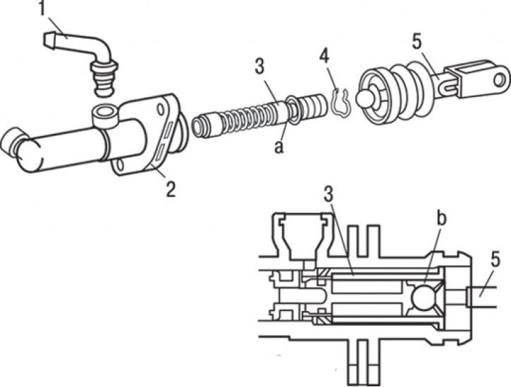
Fig. 10.10. Master cylinder of the hydraulic clutch drive of vehicles with F9Q engines: a – place of lubrication with brake fluid; b – place of application of lubricant that does not destroy rubber; 1 – nipple; 2 – clutch hydraulic drive master cylinder housing; 3 – piston assembly (lubricate with brake fluid); 4 – piston retaining ring; 5 – pusher assembly
To remove the clutch master cylinder (Fig. 10.10), perform the following operations in sequence.
1. Remove the piston retaining ring.
2. Using the special tool, remove the push rod assembly.
3. Remove the piston assembly.
4. Unscrew the coupling and disconnect the fitting.
Installation

Fig. 10.11. Correct installation of the pusher on the hydraulic clutch drive of vehicles with F9Q engines: A = (114 ±0,5) мм
Installation is carried out in the reverse order of removal. Install the pusher so that the dimension shown in Fig. 10.11 is maintained. This will simplify the procedure for adjusting the clutch pedal.