



Models without cruise control
Cordia, Tredia, Colt, Lancer, Mirage (except MPI) and Precis (except MPI)
1. On carburetor engines, remove the air filter.
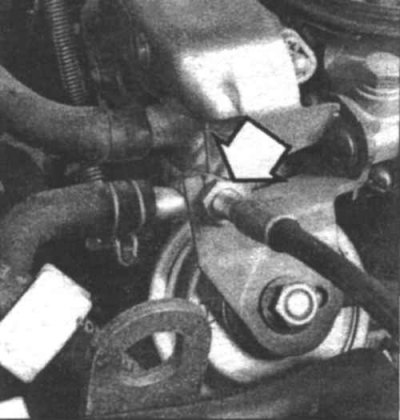
16.2 Loosen the adjusting nut (indicated by the arrow) and disconnect the accelerator cable from the bracket
2. Unscrew the adjusting nut (16.2) and remove the cable from the bracket.
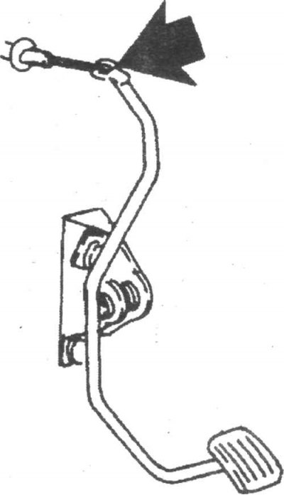
16.3a Remove the trim panel under the instrument panel and disconnect the cable at the point indicated by the arrow.
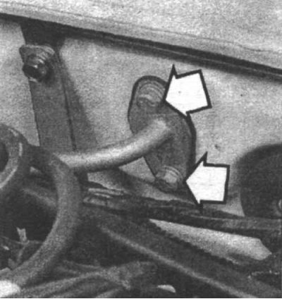
16.3b Disconnect the cable from the fire partition by unscrewing the two mounting bolts and remove the cable guide from the partition.
3. Disconnect the cable from the carburetor and gas pedal. Remove the cable from the rear wall of the engine compartment (16.3a and 16.3b).
4. Remove the cable from the vehicle.
5. Installation is carried out in the reverse order of removal.
Galant, Colt, Lancer, Mirage and Precis (MPI)
Removal and installation
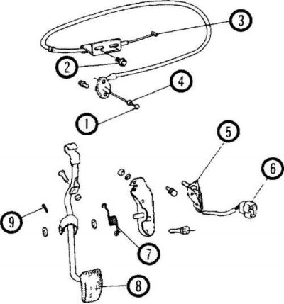
16.6 Accelerator Cable Components for Galant, Colt, Lancer, Mirage and Precis Models (without Cruise Control)
1. Cable; 2. Adjusting bolt; 3. Cable; 4. Bushing; 5. Bracket; 6. Accelerator switch connection connector (models with automatic transmission); 7. Return spring; 8. Accelerator pedal; 9. Cheka
6. Remove the cable from the brackets, disconnect it from the gas pedal and throttle body and remove it from the vehicle (16.3a, 16.3b and 16.6).
7. Installation is carried out in the reverse order of removal.
Adjustment
8. Warm up the engine and check the idle speed. Adjust it if necessary. Stop the engine.
9. Press the accelerator pedal and check that the throttle lever moves smoothly and opens the valve fully.
10. Turn on the ignition for 15 seconds.
11. Unscrew the two bolts securing the cable near the throttle body.
12. Tighten the cable and tighten the two bolts. Check that the throttle lever contacts the vacuum diaphragm rod.
Models with cruise control system
Cordia and Tredia
Accelerator pedal cable
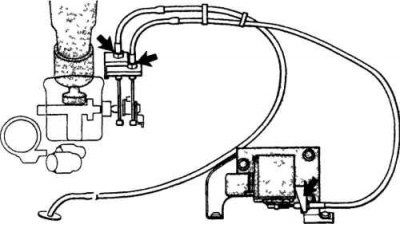
16.13 Accelerator cable fastening elements on Cordia and Tredia models with cruise control. Adjusting nuts are indicated by arrows
13. Loosen the adjusting nuts and disconnect the cable from the throttle lever and bracket (16.13).
14. Remove the cable.
15. Installation is carried out in the reverse order of removal.
Actuator cable
16 Disconnect the cable from the throttle lever and actuator and remove it from the vehicle. Installation is the reverse order of removal.
17 After installation, remove any slack from the cable by tightening the adjusting nuts while the engine is idling.
Galant
Removal and installation
18. Remove the actuator cover.
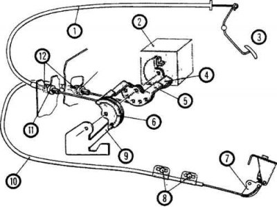
16.19 Accelerator cable fastening elements on Galant models with cruise control system
1. Accelerator cable A; 2. Cruise control actuator; 3. Accelerator pedal; 4. Switch; 5. Connecting link B; 8. Connecting link A; 7. Throttle lever; 8. Adjusting bolts; 9. Limiter; 10. Accelerator cable B; 11 Adjusting nut A; 12. Lock nut
19. Unscrew the adjusting nut and remove the cable from the bracket (16.19).
20. Disconnect the cable from the connecting link Disconnect the cable from the pedal and throttle body and remove it from the vehicle (16.3a).
21. Installation is carried out in the reverse order of removal.
Adjustment
22. Warm up the engine and check the idle speed. Adjust it if necessary. Turn off the engine.
23. Press the accelerator pedal and check that the throttle lever moves smoothly and opens the valve fully.
24. Loosen the cable adjusting nuts. Turn on the ignition for 15 seconds.
25. When the connecting link (A) touches the stop (16.19), tighten the adjusting nut (A) to adjust the cable tension so that the link (A) begins to move away from the stop, then loosen the nut (A) two turns.
26. Tighten the adjusting nut (B) to tighten the cable so that the lever on the connecting link (B) touches the lever on the link (A).
27. Loosen the two cable mounting bolts near the throttle body and tighten the cable. Tighten the intermediate link locknuts and the two bolts securing the cable near the throttle body.
Colt, Lancer, Mirage (MPI)
Removal and installation the accelerator pedal cable
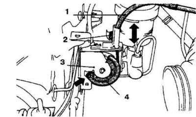
16.28 Accelerator cable fastening elements on Colt, Lancer, Mirage MPI models
1. Accelerator cable A; 2. Adjusting bolt; 3. Limiter; 4. Connecting link A
28. Remove the cable from the mounting brackets and disconnect it from the connecting link and the accelerator pedal. Remove the cable through the rear wall of the engine compartment and remove it from the vehicle. Installation is carried out in the reverse order of removal (16.28, 16.3a and 16.3b).
Removal and installation the throttle lever cable
29. Remove the cable from the mounting brackets, disconnect it from the connecting link and the throttle lever, and remove the cable from the vehicle. Installation is carried out in the reverse order of removal.
Adjustment
30. Remove the air filter.
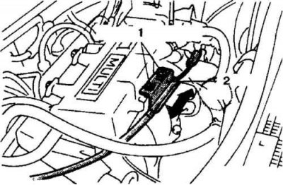
16.31 To adjust the throttle cable, tighten the adjusting bolts
1. Adjusting bolts; 2. Plate
31. Tighten the adjusting bolts to adjust the tension of the throttle lever cable so that it has a slight free play (16.31).
32. Check that the lever touches the idle speed control switch.
33. Check that the connecting link touches the stop (16.28), then loosen the accelerator pedal cable adjusting bolt and tighten the cable.
34. Check that the throttle valve opens and closes fully when the accelerator pedal is pressed.