



Removal
1. Release the pressure from the fuel system. Disconnect the negative battery cable. Drain the coolant. Disconnect all necessary hoses, wires and pipes.
2. Mark the position of the throttle position sensor and remove it.
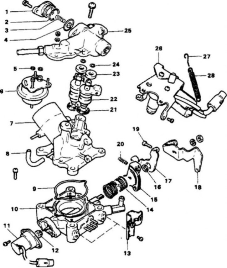
13.3 Throttle body components
1. Damper cover; 2. Sealing ring; 3. Spring; 4. Damper; 5. Sealing rings (2); 6. Fuel pressure regulator; 7. Mixer; 8. Hose; 9. Sealing ring; 10. Throttle body; 11. Throttle position sensor; 12. Connection; 13. Bracket; 14. Return spring; 15. Throttle lever 16. Ring; 17. Disconnect lever; 18. Low gear engagement lever; 19. Adjusting screw; 20. Spring; 21. Sealing rings (2); 22. Injectors; 23. Bushings (2); 24. Sealing rings (2); 25. Fastening; 26. Vacuum diaphragm; 27. Spring; 28. Return spring
3. Loosen the mounting screws and remove the injector mounts (13.3).
4. Remove the injectors from the housing. Remove the injector gaskets and other components.
Bulkhead
5. Clean all components except the vacuum diaphragm and throttle position sensor in solvent. Check that the vacuum and fuel passages are not clogged.
Installation
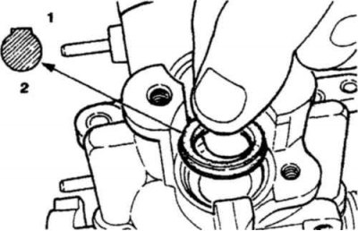
13.6a Check that the injector sealing ring is installed correctly
1. Upper side; 2. Sealing ring
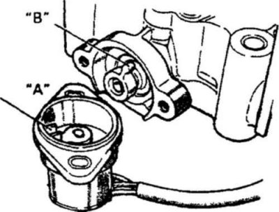
13.6b When installing the throttle position sensor, make sure that the protrusion "B" fits into the groove "A"
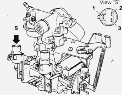
13.6v Check the resistance between terminals 1 and 2 or 2 and 3 of the throttle position sensor connector when the throttle is opened
6. Installation is carried out in the reverse order of removal (13.6a, 13.6b and 13.6c).