



Contents: Adjusting idle speed and fuel…⤓ Checking the fast idle system ⤓ Replacement and adjustment of the…⤓ Adjusting the diaphragm that…⤓ Checking the fast idle system…⤓ Checking the fuel shut-off valve,…⤓ Checking and adjusting the throttle…⤓ Checking and adjusting the…⤓ Checking the air damper ⤓ Checking and adjusting fast idle ⤓ Checking the bimetallic coil ⤓
Adjusting idle speed and fuel mixture composition
1. Look Chapter 1.
Checking the fast idle system
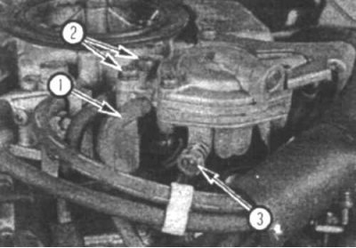
11.2a Inspect the fast idle diaphragm hose (1) for cracks and wear - disconnect the hose before checking the diaphragm; unscrew the two screws (2) to remove the diaphragm; the adjustment screw (3) is used to adjust the diaphragm
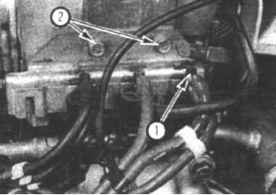
11.2b Inspect the hoses and wires connected to the fast idle system diaphragm (1) - unscrew the two bolts (2) and remove the solenoid mounting bracket
2. Check the vacuum hoses and fast idle solenoid wires (11.2a and 11.2b).
3. Connect a vacuum pump to the fast idle diaphragm. Connect a tachometer. Start the engine and let it idle.
4. Using the pump, create a vacuum of 295 mm Hg. The vacuum should increase. If not, replace the diaphragm.
Replacement and adjustment of the diaphragm of the fast idle system, which increases the engine speed when the electrical equipment or power steering system is turned on
Replacement
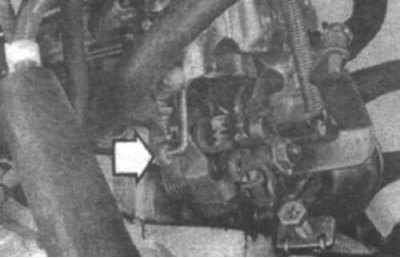
11.9 Pull the rod in the direction indicated by the arrow and disconnect the diaphragm rod from the lever
9. Disconnect the throttle lever return spring. Unscrew the two mounting screws (11.2a), disconnect the diaphragm rod from the release lever (11.9) and remove the diaphragm.
10. Install the new diaphragm and connect the vacuum hose.
Adjustment
11. Check and adjust idle speed.
12. Remove the solenoid mounting bracket (11.26). Disconnect the connection connector and connect the solenoid directly to the battery.
13. Open the throttle valve slightly and increase the engine speed to 2000 rpm, then slowly close it.
14. Check the engine speed and adjust it by turning the adjusting screw (11.2a).
15. Repeat the operations described in point 13 and check the engine speed again.
Adjusting the diaphragm that increases the engine speed when the air conditioner is turned on
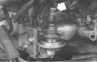
11.16 To adjust the engine speed in fast idle mode when the air conditioner is turned on, tighten the throttle valve adjusting screw (indicated by the arrow)
16. Start the engine and turn on the air conditioner. The solenoid valve should open and the vacuum in the intake manifold should open the diaphragm. Check the engine speed in this mode and adjust it, if necessary, by turning the adjusting screw (11.16).
Checking the fast idle system solenoid valve
17. Switch off the ignition. Remove the electromagnetic valve and disconnect the connection connector (11.2b).
18. Check the solenoid coil resistance and replace the valve if necessary.
Checking the fuel shut-off valve, enrichment valve, mixture control valve and float chamber vent valve
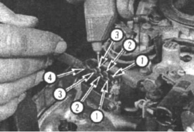
11.19a To check the solenoid valve windings, disconnect the connection connector and measure the resistance between the specified terminals (for the float chamber vent valve, measure the resistance between the specified terminal and the negative battery terminal) and compare the obtained values with the values specified in the technical specifications section:
1. Solenoid valve for adjusting the mixture composition; 2. Enrichment valve; 3. Fuel shut-off valve; 4. Float chamber ventilation valve
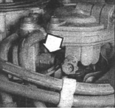
11.19b Location of fuel shut-off valve
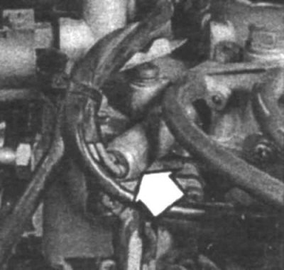
11.19v Location of enrichment valve
Information copied from the website (www.mitsubishiman.ru)
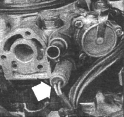
11.19g Location of the electromagnetic valve for adjusting the mixture composition
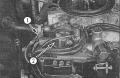
11.19d When replacing the electromagnetic valve, remove the terminal (1) from the back of the connection connector by pressing on the tab located near the terminal with a screwdriver. To remove the electromagnetic valve for ventilation of the float chamber (2), unscrew the three fastening screws
19. Disconnect the connection connector. Check the resistance of the solenoid windings and replace them if necessary (11.19a, 11.19b, 11.19c, 11.19g and 11.19d).
Checking and adjusting the throttle position sensor
Examination
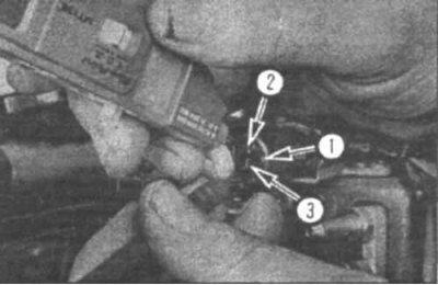
11.20 To check the throttle position sensor, disconnect the connector and measure the resistance between terminals 2 and 3
20. Check the resistance between terminals 2 and 3 of the sensor and check that the resistance changes gradually when the throttle valve is opened (11.20).
Adjustment
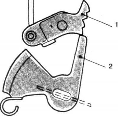
11.21 Check that the fast idle cam is free (the lever should not rest against the cam)
1. Fast idle cam; 2. Lever
21. Warm up the engine. Loosen the accelerator cable and check that the fast idle cam is free (11.21). Stop the engine.
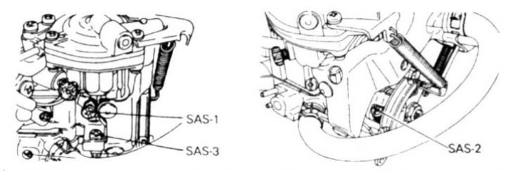
11.22 Loosen the adjusting screws SAS-1 and SAS-2 so that the throttle valve is completely closed, counting the number of revolutions
22. While counting the number of revolutions, unscrew the engine speed adjusting screws (SAS-1 and SAS-2) (11.22) so that the throttle valve is completely closed.
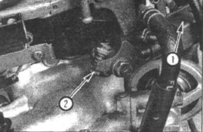
11.23a If your vehicle is equipped with this type of throttle position sensor (1), use the screw (2) to adjust it.
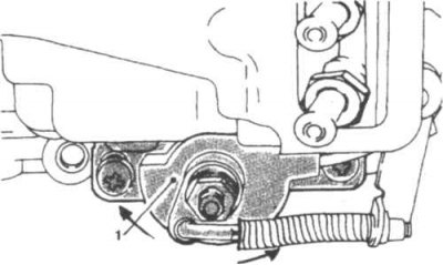
11.23b If your vehicle has this type of throttle position sensor, remove the mounting screws and adjust the sensor by turning it
1. Throttle position sensor
23. Check the sensor voltage with the ignition on between terminals 2 and 3 and adjust it if necessary by turning the adjusting screw or by turning the sensor itself (11.20, 11.23a and 11.23b).
24. Turn off the ignition.
25. Tighten the adjusting screws SAS-1 and SAS-2 by the same number of turns that they were unscrewed.
26. Adjust the accelerator cable tension. Start the engine and check the idle speed.
Checking and adjusting the carburetor damper
27. Warm up the engine and turn off all electrical equipment.
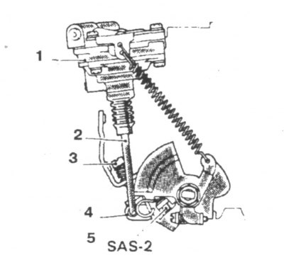
11.28 With the engine idling, open the throttle valve so that the lever touches the SAS-3 screw
1. Damper; 2. Rod; 3. SAS-3; 4. Lever; 5. SAS-2
28. Open the throttle valve fully until the rod touches the SAS-3 screw (11.28).
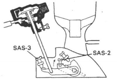
11.29 Close the throttle valve so that the SAS-2 screw touches the lever and check the engine speed
29. Close the throttle valve so that the SAS-2 screw touches the lever (11.29) and check the idle speed.
30. If the speed differs from the specified one, adjust the damper by turning the SAS-3 screw.
31. Pull the lever back and check that the engine speed slowly returns to idle speed.
Checking the air damper
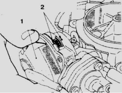
11.32 Check that the marks on the coil body and the damper match
1. Bimetallic spiral; 2. Marks
32. Check that the marks on the damper body and the bimetallic spiral (11.32) match.
33. When the engine is cold, press the accelerator pedal, the air damper should be completely closed.
34. Check that the throttle opens 1.5 mm when the engine is started. If not, check the bimetallic spiral, air damper opening diaphragms and vacuum hoses.
Checking and adjusting fast idle
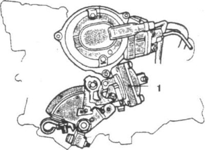
11.35 Disconnect the vacuum hose from the air damper opening diaphragm
1. Air damper opening diaphragm
35. Warm up the engine and switch off all electrical equipment of the car. Remove the air filter. Disconnect the vacuum hose from the choke opening diaphragm (11.35).
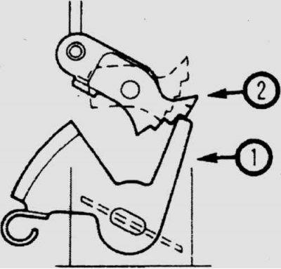
11.36a Install the lever (1) on the second tooth of the fast idle cam (2)
36. Set the lever to the second tooth of the fast idle cam. Start the engine and adjust the engine speed, if necessary, by turning the fast idle adjusting screw (11.36a).
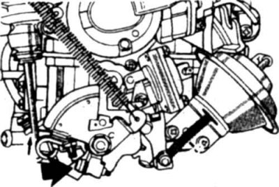
11.36b Adjust the fast idle speed by turning the adjusting screw (indicated by the arrow) and 11.36b).
Checking the bimetallic coil
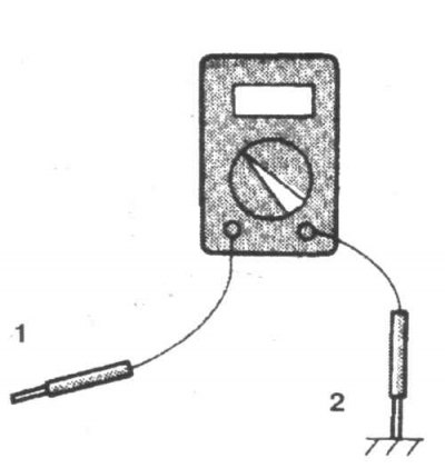
11.37 To check the bimetallic coil, disconnect the connection connector and check its resistance using an ohmmeter
1. Spiral connection connector; 2. Float chamber cover
37. Check the resistance of the coil. It should be 6 ohms at room temperature. If not, replace the coil (11.37).