



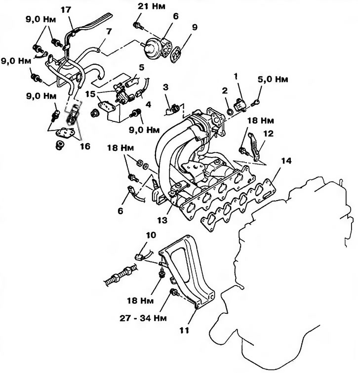
Figure 17.8. Intake manifold: 1 - Vacuum sensor; 2 - Sealing ring; 3 - Brake booster hose; 4 - Connector of the purge air control solenoid valve; 5, 7 - Vacuum hoses; 6 - Knock sensor connector; 8 - EGR valve; 9 - EGR valve gasket; 10 - Rear oxygen sensor connector; 11 - Intake manifold support; 12 - Engine bracket; 13 - Intake manifold; 14 - Intake manifold gasket; 15 - Solenoid valve for purge air control (assembled); 16 - EGR solenoid valve (assembled); 17 - Vacuum tube
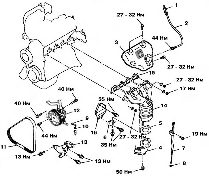
Figure 17.9a. Exhaust manifold of the 4G1 engine: 1 - Front oxygen sensor connector; 2 - Front oxygen sensor; 3 - Exhaust manifold casing; 4 - Exhaust pipe; 5 - Gasket; 6 - Exhaust manifold bracket; 7 - Oil level indicator; 8 - Sealing ring; 9 - Power steering oil pressure sensor connector; 10 - Air conditioner refrigerant pressure sensor connector; 11 - Power steering pump and air conditioning compressor drive belt; 12 - Power steering pump; 13 - Power steering pump mounting bracket; 14 - Exhaust manifold; 15 - Exhaust manifold gasket; 16 - Exhaust manifold bracket
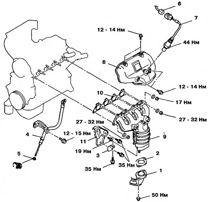
Figure 17.9b. Exhaust manifold of the 4G4 engine: 1 - Exhaust pipe; 2 - Exhaust pipe gasket; 3 - Exhaust manifold bracket; 4 - Oil level indicator; 5 - Sealing ring; 6 - Front oxygen sensor connector; 7 - Front oxygen sensor; 8 - Exhaust manifold casing; 9 - Exhaust manifold; 10 - Exhaust manifold gasket; 11 - Exhaust manifold bracket