



Contents: Technology for testing units and…⤓ Checking the Engine Control Unit…⤓ Adjusting the basic idle speed ⤓ Nozzle ⤓
Technical data of the 4G1 engine after 2001 are given in Table 17.1.
Table 17.1. Technical data of the 4G1 engine after 2001.
| Parameters | Nominal value | |
| Resistance of the inlet air temperature sensor, kOhm | 20°C | 2.3-3.0 |
| 80°C | 0.30-0.42 | |
| Oxygen sensor output voltage, V | 0.6-1.0 | |
| Oxygen sensor resistance at 20°C, Ohm | Front | 4.5-8.0 |
| Rear | 11-18 | |
Engine Diagnostic Trouble Codes
As soon as one of the following MPI fuel injection system items fails, the engine warning light (Figure 17.1) comes on. If it remains on or comes on when the engine is running, check the fault codes. The engine diagnostic fault codes are listed in Table 17.2. To check the functionality, the warning lights come on for five seconds when the ignition is turned on and then go out.
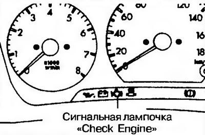
Figure 17.1. Location of the "Check Engine" indicator light
Table 17.2. Engine diagnostic trouble codes
| Fault code | The node being diagnosed |
| - | Electronic engine control unit |
| P0105 | Vacuum pressure sensor |
| P0110 | Inlet air temperature sensor |
| P0115 | Coolant temperature sensor |
| P0120 | Throttle Position Sensor |
| P0125 | Feedback system |
| P0130 | Front Oxygen Sensor |
| P0135 | Front Oxygen Sensor Heater |
| P0136 | Rear Oxygen Sensor |
| P0141 | Rear Oxygen Sensor Heater |
| P0170 | Engine power supply system |
| P0201 | Nozzle 1 |
| P0202 | Nozzle 2 |
| P0203 | Nozzle 3 |
| P0204 | Nozzle 4 |
| P0300 | Ignition failures |
| P0301 | Cylinder 1 misfire |
| P0302 | Cylinder 2 misfire |
| P0303 | Cylinder 3 misfire |
| P0304 | Cylinder 4 misfire |
| P0325 | Knock sensor |
| P0335 | Crankshaft angle sensor |
| P0340 | Camshaft Angle Sensor |
| P0403 | Solenoid valve with exhaust gas recirculation system |
| P0420 | Catalyst |
| P0421 | Catalyst |
| P0443 | Purge air control solenoid valve |
| P0500 | Vehicle speed sensor |
| P0505 | Idle Speed Control System |
| R1610 | Electronic engine immobilizer |
Technology for testing units and assemblies
The technology for checking units and assemblies is given in Table 17.3.
Table 17.3. Checking units and assemblies
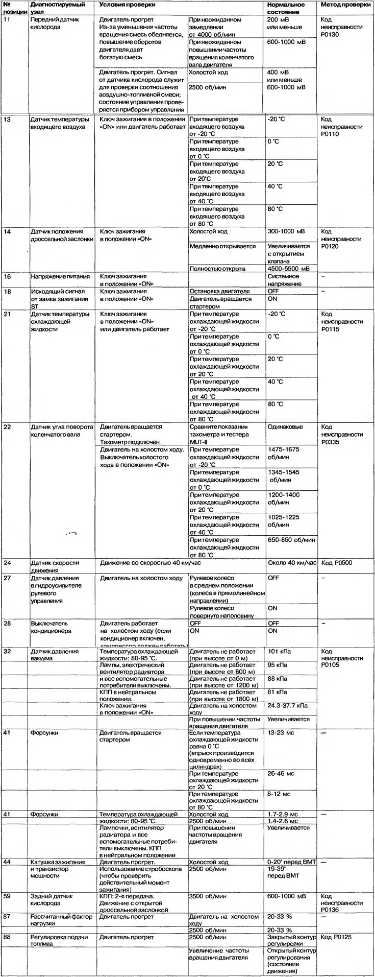
Checking the Engine Control Unit Connector
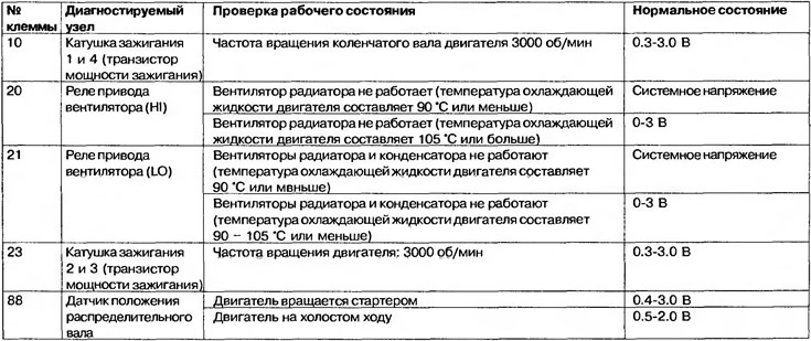
The voltage values at the terminals of the engine control unit connector are shown in Table 17.4.
Table 17.4. Voltage values at the terminals of the engine control unit connector
Adjusting the basic idle speed
1. The standard idle speed is adjusted by the manufacturer using the speed adjusting bolt (SAS), so there is no need for such adjustment.
2. If the adjustment is changed intentionally, the idle speed may increase or decrease if the engine is loaded, such as by an air conditioner. In this case, the adjustment should be made as described below.
3. Adjustment is carried out only after the functionality of the spark plugs, injectors, idle drive with booster, compression, etc. has been checked.
4. Connect the MUT-II tester to the diagnostic (16-pin) connector.
5. Start the engine and let it idle.
6. Select item 30 of the tester verification test.
Note: The ISC stepper motor remains in the initial stage so that the basic idle speed can be adjusted.
7. Check the idle speed. Nominal value: 750±50 rpm.
Attention! For a new car (with a mileage of less than 500 km), the engine speed may be 20-100 rpm lower, but adjustment is not necessary in this case. If the engine stalls or the engine speed is too low, although the car's mileage is already more than 500 km, the throttle valve is probably clogged and needs to be cleaned.
8. If the measured value does not correspond to the nominal value, adjust it with the speed adjusting bolt (SAS) (Figure 17.2).
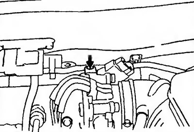
Figure 17.2. Location of the Speed Adjusting Bolt (SAS)
9. Press the reset button of the MUT-II tester and take the ISC stepper motor out of the test mode.
Attention! If you do not do this, the testing mode will continue for 27 minutes.
10. Turn off the ignition.
11. Disconnect the MUT-II tester.
12. Start the engine again and let it idle for 10 minutes. Check the idle speed.
Nozzle
The nozzle is shown in Figure 17.3.
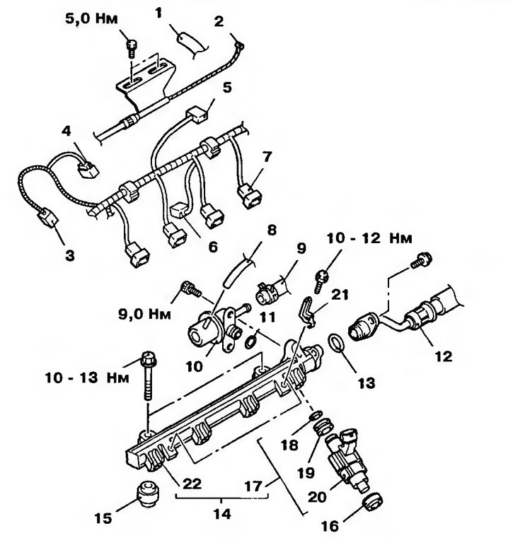
Figure 17.3. Nozzle: 1 - Crankcase ventilation tube; 2 - Accelerator pedal cable; 3 - Rear oxygen sensor wiring connector; 4 - Knock sensor wiring connector; 5 - Vacuum sensor connector; 6 - EGR solenoid valve wiring connector; 7 - Injector wiring connector; 8 - Vacuum tube; 9 - Fuel drain line; 10 - Fuel pressure regulator; 11, 13, 18 - Sealing rings; 12, 22 - Fuel injection lines; 14 - Fuel distributor with injector; 15, 16 - Rubber cushions; 17 - Injector assembly; 19 - Rubber bushing; 20 - Nozzle; 21 - Wiring harness mounting bracket.