



Contents: Checking the coolant temperature…⤓ Checking the coolant temperature…⤓ Checking the FBC/MPI Carburetor…⤓
Petrol engines have 2 temperature sensors, while diesel engines are equipped with one dual temperature sensor. They consist of an NTC element (NTC = negative temperature coefficient), which decreases its resistance as the temperature increases.
- Gasoline engine: Both sensors are screwed into the thermostat housing. From the single-pole sensor, temperature information is transmitted to the temperature gauge on the instrument panel. If the sensor is defective, the gauge does not show at all or gives incorrect readings. The signal from the two-pin temperature sensor goes to the control unit of the electronic carburetor or fuel injection device.
- Diesel engine: From contact 1 the signal goes to the coolant temperature gauge, from contact 2 to the glow plug system.
Checking the coolant temperature gauge sensor
Remove the connector from the temperature sensor. Do this by pulling the connector, not the wires.
The assistant should turn on the ignition and observe the temperature gauge readings.
Briefly touch the sensor connector to the ground; the indicator arrow should move to its maximum position.
If there is no maximum reading, check the reliability of the installation and the contacts of the sensor connector. Check the electrical wires and connection points on the dashboard according to the electrical diagram. If there is a maximum reading, remove and replace the sensor.
Caution: To prevent coolant from leaking out when removing the sensor, it should first be partially drained and collected.
Apply a sealant, such as MITSUBISHI 3M-4171, to the sensor threads.
Screw in and tighten the temperature sensor to 10 Nm. Put on the connector.
Add coolant, see p. 3.3.
Make a test drive and check the tightness of the temperature sensor connection.
Checking the coolant temperature sensor in a dismantled state
Remove the connector, unscrew the temperature sensor.
Caution: To prevent coolant from leaking out when removing the sensor, it should first be partially drained and collected.
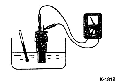
Connect an ohmmeter and warm up the temperature sensor in a water bath.
Required value for 1.2/1.3/1.5/1.6 l engines (16-valve): 104 ±13.5 Ohm at 70°C.

Required value for diesel engines:
- Element I: 104 ±13.5 ohms at 70°C
- Element II: 3.25 ±0.33 kOhm at 20°C
Apply a sealant, such as MITSUBISHI 3M-4171, to the threads of the temperature sensor.
Screw in and tighten with a torque of 10 Nm, for diesel engines - 30 Nm temperature sensor. Put on the connector.
Add coolant, see p. 3.3.
Make a test drive and check the tightness of the temperature sensor connection.
Checking the FBC/MPI Carburetor Temperature Sensor
Remove the connector, unscrew the temperature sensor.
Caution: To prevent coolant from leaking out when removing the sensor, it should first be partially drained and collected.
Connect an ohmmeter and warm up the temperature sensor in a water bath.
Required value: 2.45 ±0.24 kOhm at 20°C, 296 ±32 Ohm at 80°C.
Apply a sealant, such as MITSUBISHI 3M-4171, to the threads of the temperature sensor.
Screw in the temperature sensor and tighten it to 30 Nm. Put on the connector.
Add coolant, see p. 3.3.
Make a test drive and check the tightness of the temperature sensor connection.