



Disassembling the gearbox
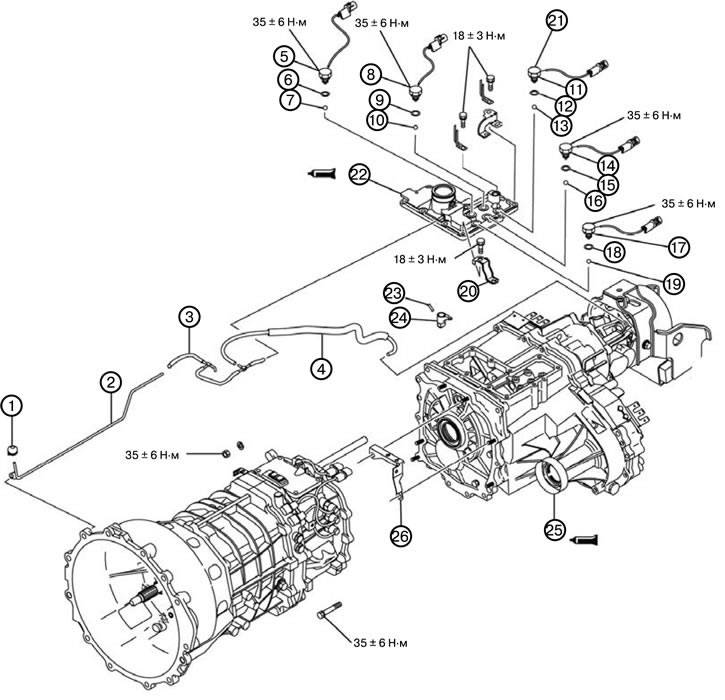
1. Remove the ventilation cover (1).
2. Remove the ventilation tube (2).
3. Remove the vacuum hose (3).
4. Remove the vacuum hose (4).
5. Remove the 4LLC mode switch (5).
6. Remove the gasket (6).
7. Remove the steel ball (7).
8. Remove the 2WD mode switch (8).
9. Remove the gasket (9).
10. Remove the steel ball (10).
11. Remove the center differential lock switch (11).
12. Remove the gasket (12).
13. Remove the steel ball (13).
14. Remove the 4H mode switch (14).
15. Remove the gasket (15).
16. Remove the steel ball (16).
17. Remove the 2WD/4WD mode switch (17).
18. Remove the gasket (18).
19. Remove the steel ball (19).
20. Remove the wiring bracket (20).
21. Remove the wiring bracket (21).
22. Remove the control housing (22).
23. Remove the spring pin (23).
24. Remove the switch (24).
25. Remove the transfer case (25).
26. Disconnect the connector bracket (26).
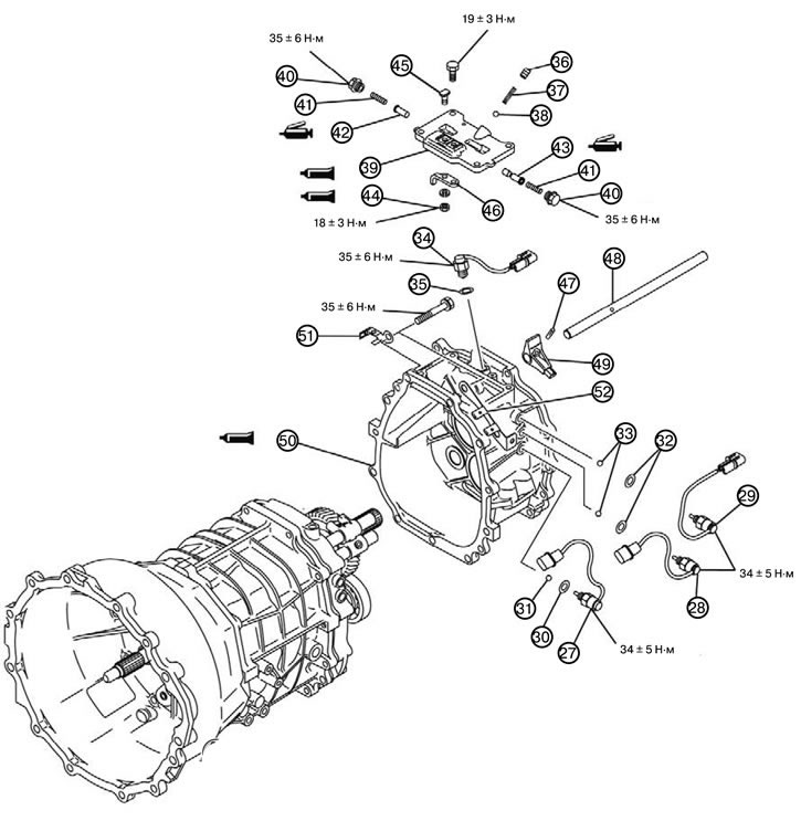
27. Remove the fifth and reverse gear engagement sensor (27).
28. Remove the third and fourth gear engagement sensor (28).
29. Remove the first and second gear engagement sensor (29).
30. Remove the gasket (30).
31. Remove the steel ball (31).
32. Remove the gasket (32).
33. Remove the steel ball (33).
34. Remove the 4WD mode switch (34).
35. Remove the gasket (35).
36. Remove the resistance spring plug (36).
37. Remove the resistance spring (37).
38. Remove the steel ball (38).
39. Remove the top cover (39).
40. Unscrew the seal bolt (40).
41. Remove the return spring to the neutral position (41).
42. Remove plunger A of the return spring to the neutral position (42).
43. Remove plunger B of the return spring to the neutral position (43).
44. Unscrew the nut (44).
45. Unscrew the special bolt (45).
46. Remove the limit bracket (46).
47. Remove the spring pin (47). Set the control finger to the neutral position and remove the spring pin.
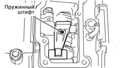
48. Remove the control shaft (48).
49. Remove the control finger (49).
50. Remove the transfer case housing adapter (50).
51. Remove the connector bracket (51).
52. Remove the connector bracket (52).
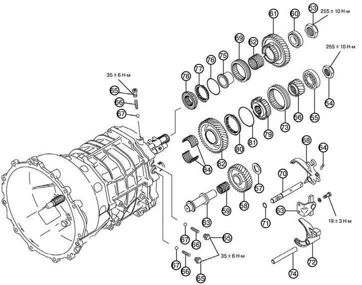
53. Unscrew the lock nut (53).
54. Unscrew the lock nut (54).
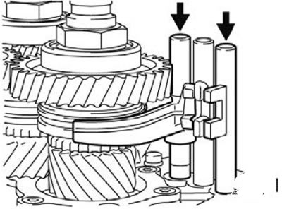
1) Install the shift forks as shown in the figure.
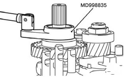
2) Unscrew the main shaft lock nut using the special wrench MD998835.
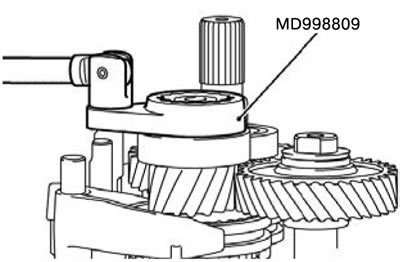
3) Unscrew the counter shaft gear lock nut using the special wrench MD998809.
55. Remove the ball bearing (55).
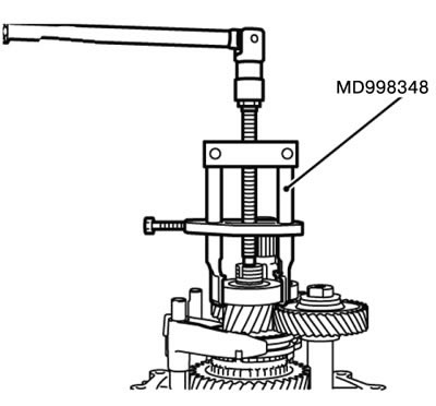
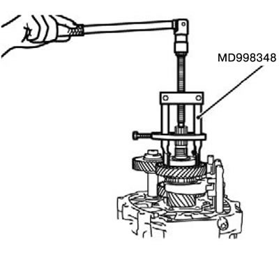
1) Remove the ball bearing from the counter shaft gear block using special tool MD998348.
56. Remove the counter return gear (56).
57. Remove the support washer (57).
58. Remove the reverse intermediate gear (58).
59. Remove the needle bearing (59).
60. Remove the ball bearing (60).
1) Remove the ball bearing from the main shaft using special tool MD998348.
61. Remove the reverse gear (61).
62. Remove the needle bearing (62).
63. Remove the fifth speed engagement fork (63).
64. Remove the spring pin (64).
65. Remove the disc spring (65).
66. Remove the disc plug (66).
67. Remove the steel ball (67).
68. Remove the reverse gear engagement fork (68).
69. Remove the reverse synchronizer ring gear (69).
70. Remove the reverse gear engagement shaft (70).
71. Remove the spring ring (71).
72. Remove the fifth gear engagement fork (72).
73. Remove the fifth gear synchronizer ring gear (73).
74. Remove the fifth gear shift shaft (74).
75. Remove the reverse gear brake gear bearing sleeve (75).
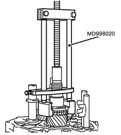
1) Install special tool MD998020 to the reverse brake gear.
2) Tighten the central bolt of the special tool, and remove the reverse gear brake gear bearing sleeve, synchronizer ring and synchronizer spring assembly.
76. Remove the synchronizer spring (76).
77. Remove the synchronizer ring (77).
78. Remove the reverse brake gear (78).
79. Remove the fifth gear synchronizer sleeve (79).
80. Remove the synchronizer ring (80).
81. Remove the synchronizer spring (81).
82. Remove the fifth gear counter gear (82).
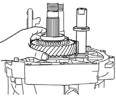
83. Remove the return intermediate gear shaft (83).
1) Raise the counter gear of the fifth gear to the cut of the return intermediate gear shaft and remove them as an assembly.
84. Remove the needle bearing (84).
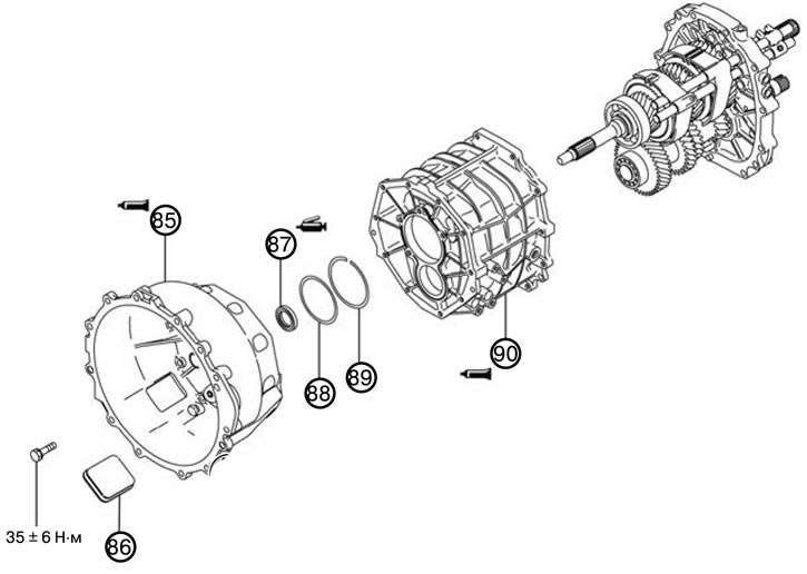
85. Remove the clutch housing (85).
86. Remove the inspection hole cover (86).
87. Remove the oil seal (87).
88. Remove the washer (88).
89. Remove the spring ring (89).
1) Remove the spring rings from the rear bearing mounting surface by moving the main shaft and counter shaft gear block away from the intermediate plate.
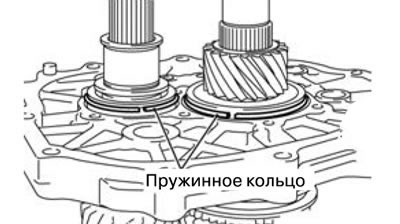
90. Remove the gearbox housing (90).
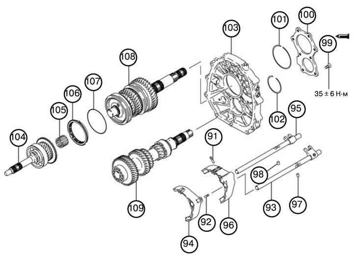
91. Remove the spring pin (91).
92. Remove the spring pin (92).
93. Remove the third-fourth gear engagement fork shaft (93).
94. Remove the third-fourth gear engagement fork (94).
95. Remove the first-second gear engagement fork shaft (95).
96. Remove the first-second gear engagement fork (96).
97. Remove the lock plunger (97).
98. Remove the lock plunger (98).
99. Unscrew the seal bolt (99).
100. Remove the rear bearing holder (100).
101. Remove the spring ring (101).
102. Remove the spring ring (102).
103. Remove the intermediate plate (103).
1) Lightly tap the intermediate plate with a plastic hammer or suitable tool, remove the intermediate plate from the main drive gear, main shaft and counter shaft gear block.
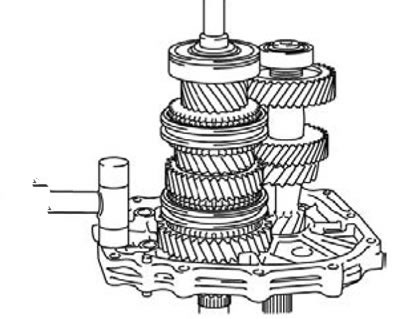
104. Remove the main drive shaft (104).
105. Remove the needle bearing (105).
106. Remove the synchronizer ring (106).
107. Remove the synchronizer spring (107).
108. Remove the main shaft (108).
109. Remove the counter shaft with the gear block (109).