



Removal the gearbox assembly
Attention: To avoid damage to the paintwork, it is necessary to cover the body fenders with some material.
Note: Mark the wires and tubes to avoid incorrect installation.
1. Remove the gear shift lever assembly.
2. Remove the front and rear engine crankcase guards.
3. Drain the transmission oil.
4. Drain the oil from the transfer case.
5. Remove the front exhaust pipe and catalytic converter.
6. Remove the rear propeller shaft.
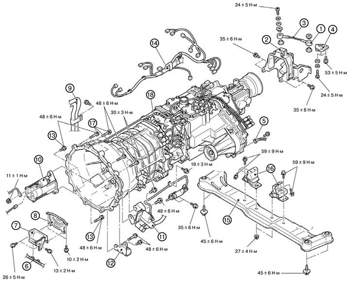
7. Remove the front propeller shaft.
1) Support crossmember #2 with a transmission jack and disconnect the connection between crossmember #2 assembly and the front part of the frame.
Caution: Be careful not to damage the vacuum hoses.
2) Lower cross member No. 2 so that it becomes possible to remove the front propeller shaft.
3) Remove the front propeller shaft, install the cross beam No. 2 assembly on the front part of the frame.
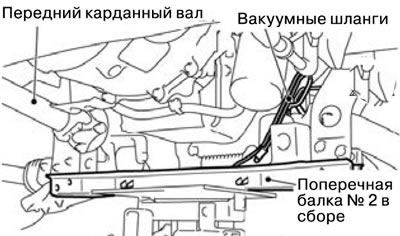
8. Disconnect the tension cable connection (1).
9. Remove the dynamic shock absorber (2).
10. Remove the tension cable (3).
11. Remove the tension cable bracket (4).
12. Remove the ground connection (5).
13. Disconnect the battery wiring connection (6).
14. Remove the left oil pan cover assembly (7).
15. Remove the dust cover (8).
16. Disconnect the heater hose connection (9).
17. Remove the starter (10).
18. Remove the clutch release cylinder and disconnect the clutch chamber connection (11).
19. Disconnect the clutch release bearing connection.
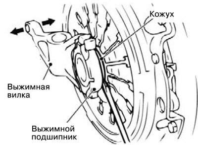
1) Remove the inspection hole cover of the clutch housing.
2) Press the release fork with your hand in direction A, insert a flat-head screwdriver between the release bearing and the housing.
Caution: If turning the screwdriver is difficult, remove the screwdriver and press the release fork two or three times in the direction shown in the figure.
3) Turn the screwdriver 90° and separate the release bearing from the housing.
Note: The release fork will move in direction B under the action of the return spring after the release bearing is removed.
20. Remove the exhaust system mounting bracket (12).
21. Unscrew the lower gearbox connecting bolts (13).
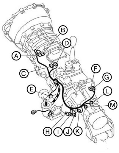
22. Disconnect the gearbox wiring connector (14).
1) Lower the transmission so that the electrical wiring connectors can be disconnected, and then disconnect the connectors.
2) Position the disconnected transmission wiring as it is located on the vehicle.
| Code | Name of the connector |
| A | Reversing light switch |
| IN | 3rd and 4th speed sensor |
| WITH | 1st and 2nd speed sensor |
| D | Selected speed sensor |
| E | Front propeller shaft speed sensor |
| F | 2WD operation detection sensor |
| G | Detection sensor 4LLc |
| N | Center differential lock detection sensor |
| I | Detection sensor 4H |
| J | 2WD/4WD detection sensor |
| TO | Shift drive |
| L | Rear propeller shaft speed sensor |
| M | Vehicle speed sensor |
23. Support the gearbox using a transmission jack.
24. Remove the central cross beam of the gearbox mount (15).
25. Remove the gearbox mounting insulator assembly (16).
26. Unscrew the upper gearbox connecting bolts (17).
27. Remove the gearbox with the transfer case assembly (18).
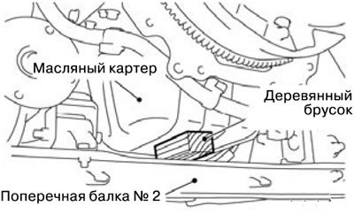
Caution: Place a block of wood between crossmember No. 2 and the engine oil pan to secure the engine and prevent damage when removing the transmission.
Installing the gearbox assembly
Attention: To avoid damage to the paintwork, it is necessary to cover the body fenders with some material.
Note: When installing, tighten the bolts to the tightening torques shown in the figure.
1. Install the gearbox with the transfer case assembly (18).
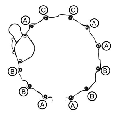
2. Tighten the upper gearbox connecting bolts (17).
Please note: Connecting bolts come in different sizes. Be careful not to confuse them.
| Bolt | Dxl, mm |
| A | 10x25 |
| IN | 10x45 |
| WITH | 10x50 |
3. Install the gearbox mounting insulator assembly (16).
4. Install the central gearbox mounting cross beam (15).
5. Remove the transmission jack.
6. Connect the gearbox wiring connector (14).
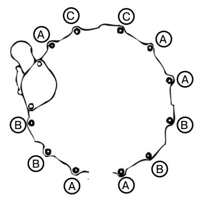
7. Tighten the lower gearbox connecting bolts (13).
Please note: Connecting bolts come in different sizes. Be careful not to confuse them.
| Bolt | Dxl, mm |
| A | 10x25 |
| IN | 10x45 |
| WITH | 10x50 |
8. Install the exhaust system mounting bracket (12).
9. Connect the clutch release bearing connection.
10. Install the clutch release cylinder and disconnect the clutch chamber connection (11).
11. Install the starter (10).
12. Connect the heater hose connection (9).
13. Install the dust cover (8).
14. Install the left oil pan cover assembly (7).
15. Connect the battery wiring connection (6).
16. Install the ground connection (5).
17. Install the tension cable bracket (4).
18. Install the tension cable (3).
19. Install the dynamic shock absorber (2).
20. Connect the tension cable connection (1).
21. Install the front propeller shaft.
22. Install the rear propeller shaft.
23. Install the front exhaust pipe and catalytic converter.
24. Fill the transfer case with oil.
25. Fill with transmission oil.
26. Install the front and rear engine crankcase guards.
27. Install the gear shift lever assembly.