



Gearbox assembly
Note: When assembling, tighten the bolts to the tightening torques shown in the figure.
1. Perform adjustment before assembly.
1) Make adjustments using soldering.
(1) Install the main drive gear into the gearbox housing.
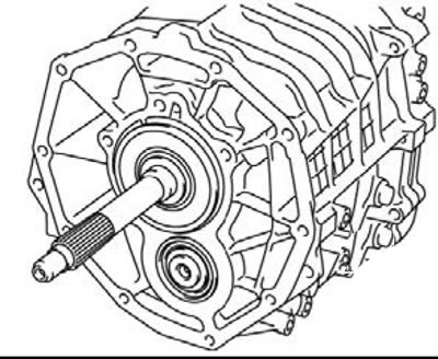
(2) Install the solders (diameter 1 mm, and about 10 mm long) on the ball bearing as shown in the figure.
(3) Install the clutch housing and tighten the bolts to the recommended tightening torque of 35±6 N·m.
(4) Remove the clutch housing and remove the solders.
(5) If the adhesions are not damaged, use thicker adhesions (diameter 1.6 mm, and about 10 mm long) and repeat steps 2 and 4.
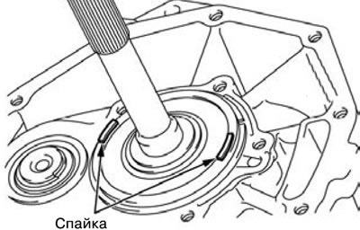
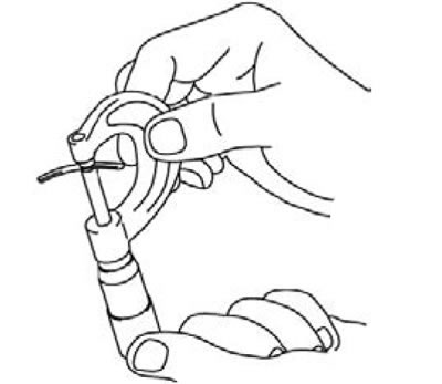
(6) Measure the thickness of damaged adhesions with a micrometer and select washers according to standard values.
Washer thickness:
- from (T1 - 0) to (T1 - 0.1)
- T1 - Thickness of broken adhesion, mm.
- Standard value: 0 - 0.1 mm.
2) Perform adjustment using a gap measuring tool.
(1) Install the main drive gear into the gearbox housing.
(2) Install adjusting washers of minimum thickness.
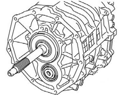
(3) Install the gap measuring tool (length about 10 mm) as shown in the figure.
(4) Install the clutch housing and tighten the bolts to the recommended tightening torque of 35±6 Nm.
(5) Remove the clutch housing and remove the damaged gauge tool.
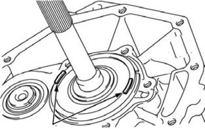
Instrument for measuring devices
(6) Replace the washers with thicker ones and repeat steps 3 through 5 if the clearance gauge is not damaged.
(7) Measure the width of the damaged clearance gauge at its widest part using the scale printed on the clearance gauge package.
Washer thickness:
- from (T2 + T3 - 0) to (T2+ T3 - 0.1)
- T3 - Thickness of the washer used for measurements, mm
- Standard value: 0 - 0.1 mm.
2. Install the counter shaft with the gear block (109).
3. Install the main shaft (108).
4. Install the synchronizer spring (107).
5. Install the synchronizer ring (106).
6. Install the needle bearing (105).
7. Install the main drive shaft (104).
8. Install the intermediate board (103).
1) Install the main shaft and counter shaft with the gear block into the gearbox housing.
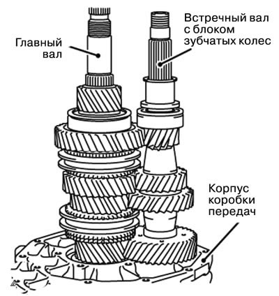
2) Install the intermediate plate using a plastic hammer.
Note: Push in the intermediate plate until the main shaft and countershaft bearing snap ring grooves are aligned with the rear bearing retainer mounting surface.
3) Install the spring ring.
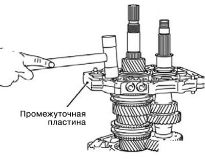
9. Install the spring ring (102).
10. Install the spring ring (101).
11. Install the rear bearing holder (100).
12. Tighten the seal bolt (99).
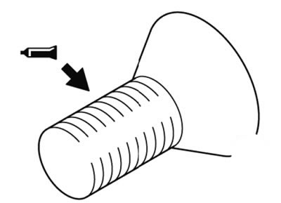
1) Apply special lubricant to the bolt threads.
Special lubricant: ZM STUD Locking No. 4170 or similar.
Note: Do not apply grease to new bolts as they are already lubricated.
13. Install the locking plunger (98).
14. Install the locking plunger (97).
15. Install the first-second gear engagement fork (96).
16. Install the first-second gear shift fork shaft (95).
17. Install the third-fourth gear engagement fork (94).
18. Install the third-fourth gear shift fork shaft (93).
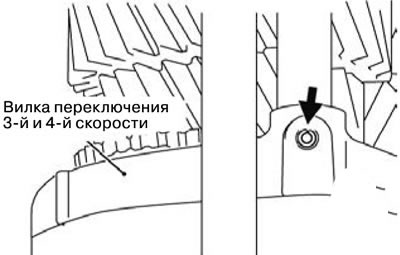
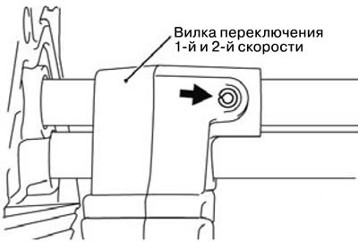
19. Install the spring pin (92).
20. Install the spring pin (91).
1) Install the spring pin so that it is parallel to the shift shaft.
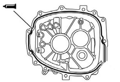
21. Install the gearbox housing (90).
1) Apply special grease to the gearbox housing before installation.
Special grease: Mitsubishi Part No. MD997740 or equivalent.
22. Install the spring ring (89).
23. Install the washer (88).
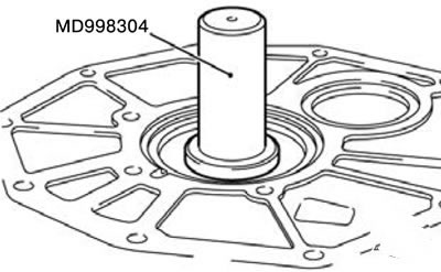
24. Install the oil seal (87).
1) Install the oil seal into the clutch housing using special tool MD998304.
2) Apply special grease to the edges of the seal.
Special grease: Mitsubishi Part No. 0101011 or equivalent.
25. Install the inspection hole cover (86).
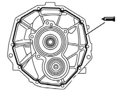
26. Install the clutch housing (85).
Caution: Be careful not to damage the seal with the splines of the main drive shaft.
1) Apply special grease to the clutch housing before installation.
Special grease: Mitsubishi Part No. MD997740 or equivalent.
27. Install the needle bearing (84).
28. Install the return intermediate gear shaft (83).
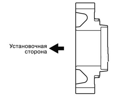
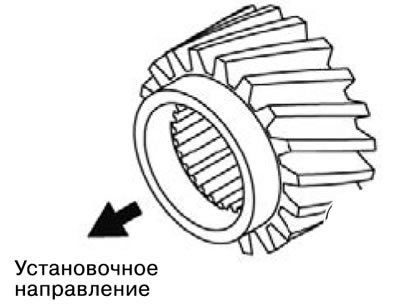
29. Install the counter gear of the fifth gear (82).
1) Before assembly, make sure that the counter gear of the fifth gear is located in the correct direction.
30. Install the synchronizer spring (81).
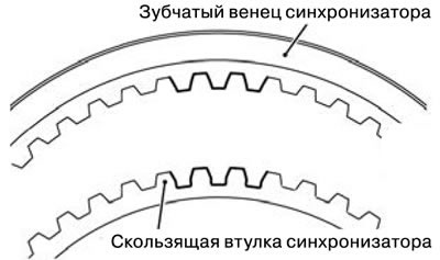
31. Install the synchronizer ring (80).
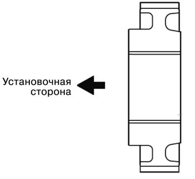
32. Install the fifth gear synchronizer sleeve (79).
1) Before assembly, make sure that the fifth gear synchronizer sleeve is positioned in the correct direction.
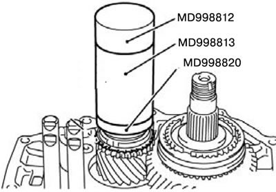
33. Install the reverse brake gear (78).
1) Install the reverse brake gear using special tool MD998812, MD998813 and MD998820.
34. Install the synchronizer ring (77).
35. Install the synchronizer spring (76).
36. Install the reverse gear bearing sleeve (75).
1) Install the reverse gear bearing sleeve using special tool MD998812, MD998813 and MD998819.
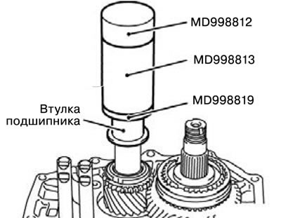
37. Install the fifth gear shift shaft (74).
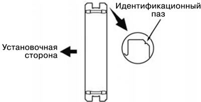
38. Install the fifth gear synchronizer ring gear (73).
1) Before assembly, make sure that the fifth gear synchronizer ring gear is positioned in the correct direction.
39. Install the fifth gear engagement fork (72).
40. Install the spring ring (71).
41. Install the reverse gear engagement shaft (70).
42. Install the synchronizer ring gear (69).
1) Before assembly, make sure that the reverse gear synchronizer ring gear is positioned in the correct direction.
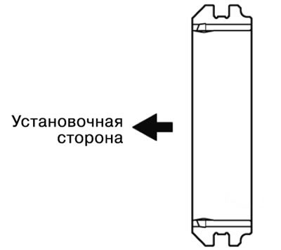
43. Install the reverse gear engagement fork (68).
44. Install the steel ball (67).
45. Install the disc spring (66).
1) Install the disc spring with the thin end facing the steel ball.
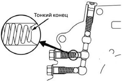
46. Install the disc plug (65).
47. Install the spring pin (64).
1) Install the spring pin so that it is parallel to the shift shaft.
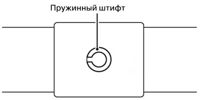
48. Install the fifth speed engagement fork (63).
49. Install the needle bearing (62).
50. Install the reverse gear (61).
1) Install the reverse gear as shown in the figure.
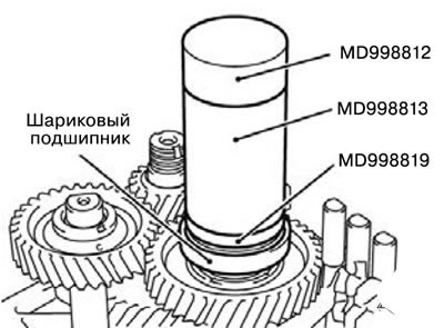
51. Install the ball bearing (60).
1) Install the ball bearing using special tool MD998812, MD998813 and MD998819.
52. Install the needle bearing (59).
53. Install the reverse intermediate gear (58).
1) Before installation, make sure the gear is in the correct position.
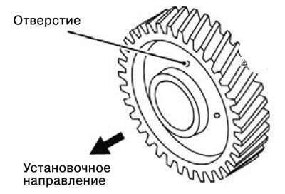
54. Install the support washer (57).
55. Install the counter return gear (56).
1) Before installation, make sure the gear is in the correct position.
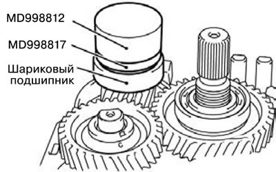
56. Install the ball bearing (55).
1) Install the ball bearing using special tool MD998812 and MD998817.
57. Tighten the lock nut (54).
58. Tighten the lock nut (53).
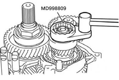
1) Install the shift forks as shown in the figure.
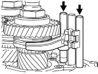
2) Tighten the main shaft lock nut using the special wrench MD998835 to the recommended tightening torque of 255±10 Nm.
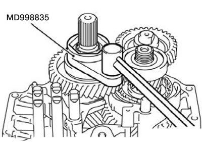
3) Tighten the counter shaft lock nut with the gear block using the special wrench MD998809 to the recommended tightening torque of 255±10 N·m.
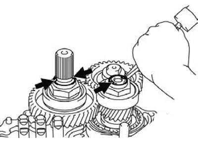
4) Lock the two lock nuts using a punch.
59. Install the connector bracket (52).
60. Install the connector bracket (51).
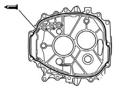
61. Install the transfer case housing adapter (50).
1) Apply special grease to the mounting surface of the transfer case housing adapter. Special grease: Mitsubishi Part No. MD997740 or equivalent.
62. Install the control finger (49).
63. Install the control shaft (48).
64. Install the spring pin (47).
65. Install the limit bracket (46).
66. Tighten the special bolt (45).
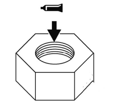
67. Tighten the nut (44).
1) Apply special grease to the bolt as shown in the figure.
Special grease: Mitsubishi Part No. MD997740 or equivalent.
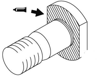
2) Apply special grease to the nut as shown in the figure.
Special lubricant: ZM AAD Part No. 2353 or similar.
68. Set plunger B of the return spring to the neutral position (43).
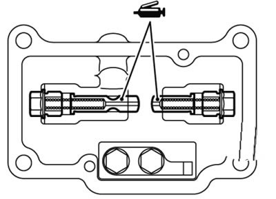
69. Set plunger A of the return spring to the neutral position (42).
1) Apply grease to the surface of the plunger. Then install the return spring plunger into the top cover and secure with the spring.
Special grease: Mitsubishi Part No. 0101011 or equivalent.
70. Set the return spring to the neutral position (41).
71. Tighten the seal bolt (40).
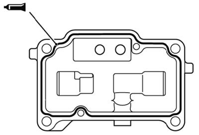
72. Install the top cover (39).
1) Apply special grease to the mounting surface of the top cover.
Special grease: Mitsubishi Part No. MD997740 or equivalent.
73. Install the steel ball (38).
74. Install the resistance spring (37).
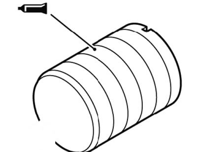
75. Install the resistance spring plug (36).
1) Apply special grease to the resistance spring plug as shown in the figure.
Special lubricant: ZM ATD Part No. 8660 or similar.
76. Install the gasket (35).
77. Set the 4WD mode switch (34).
78. Install the steel ball (33).
79. Install the gasket (32).
80. Install the steel ball (31).
81. Install the gasket (30).
82. Install the first and second gear engagement sensor (29).
83. Install the third and fourth gear engagement sensor (28).
84. Install the fifth and reverse gear engagement sensor (27).
85. Connect the connector bracket (26).
86. Install the transfer case (25).
1) Apply special grease to the mounting surfaces of the transfer case adapter.
Special grease: Mitsubishi Part No. MD997740 or equivalent.
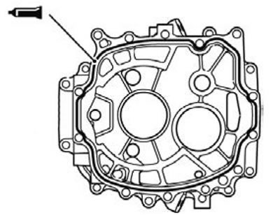
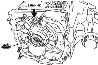
2) Apply special grease to the end surface of the transfer case input gear as shown in the figure.
Special grease: Mitsubishi Part No. 0101011 or equivalent.
3) Assemble the transfer case and gearbox so as not to damage the oil seal.
87. Install the switch (24).
88. Install the spring pin (23).
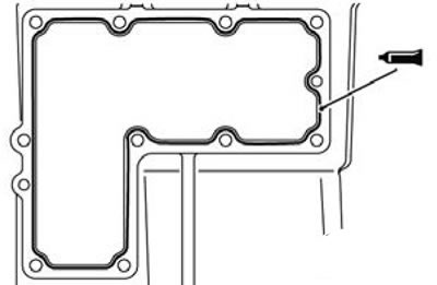
89. Install the control housing (22).
1) Apply special grease to the indicated points of the control housing.
Special grease: Mitsubishi Part No. MD997740 or equivalent.
90. Install the wiring bracket (21).
91. Install the wiring bracket (20).
92. Install the steel ball (19).
93. Install the gasket (18).
94. Set the 2WD/4WD mode switch (17).
95. Install the steel ball (16).
96. Install the gasket (15).
97. Set the switch to 4H mode (14).
98. Install the steel ball (13).
99. Install the gasket (12).
100. Install the center differential lock switch (11).
The article was taken from the website (mitsubishiman)
101. Install the steel ball (10).
102. Install the gasket (9).
103. Set the 2WD mode switch (8).
104. Install the steel ball (7).
105. Install the gasket (6).
106. Set the switch to 4LLC mode (5).
1) Install the switches according to the table.
| Mounting position | Tube color | Connector color |
| A | Blue | Black |
| IN | Black | Brown |
| WITH | Black | Black |
| D | Green | White |
| E | Blue | Brown |
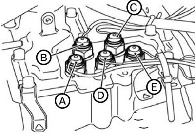
107. Install the vacuum hose (4).
108. Install the vacuum hose (3).
109. Install the ventilation tube (2).
110. Install the ventilation cover (1).