



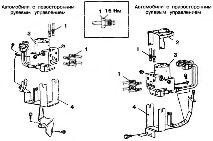
Figure 14.38. Hydraulic control unit: 1 - Brake pipes; 2 - Wiring connector mounting bracket; 3 - Hydraulic control unit; 4 - Hydraulic unit mounting bracket
The connection of the brake pipes to the hydraulic control unit is shown in Figure 14.39.
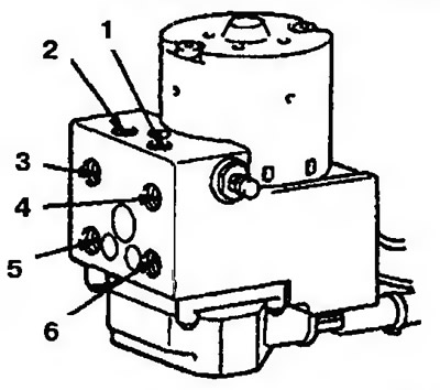
Figure 14.39. Connecting the brake pipes to the hydraulic control unit: 1 - To the brake booster valve (right); 2 - To the brake booster valve (left); 3 - From the main brake cylinder (first piston); 4 - From the main brake cylinder (second piston); 5 - To the front right wheel brake mechanism; 6 - To the front left wheel brake mechanism
The original article is on the website: mitsubishiman.ru