



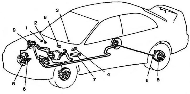
Figure 14.34a. Schematic diagram of the ABS anti-lock braking system for left-hand drive vehicles: 1 - ABS valve relay; 2 - ABS drive relay; 3 - ABS warning light; 4 - Brake light switch; 5 - Wheel speed sensor rotor; 6 - Wheel speed sensor; 7 - ABS control unit; 8 - Diagnostic connector; 9 - Hydraulic block
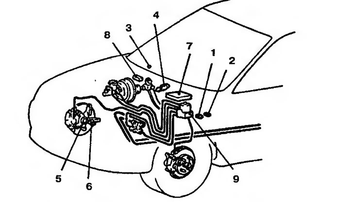
Figure 14.346. Schematic diagram of the ABS anti-lock braking system for right-hand drive vehicles: 1 - ABS valve relay: 2 - ABS drive relay; 3 - ABS warning light; 4 - Brake light switch; 5 - Wheel speed sensor rotor; 6 - Wheel speed sensor; 7 - ABS control unit; 8 - Diagnostic connector; 9 - Hydraulic block
Table 14.3. Technical characteristics of the anti-lock braking system ABS
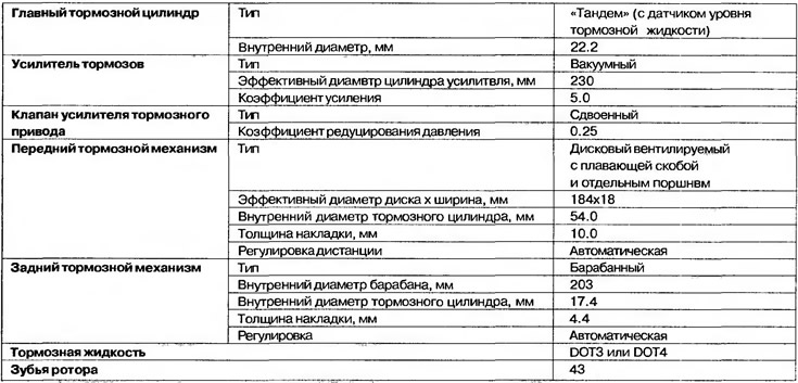
Table 14.4. Technical data of the anti-lock braking system ABS

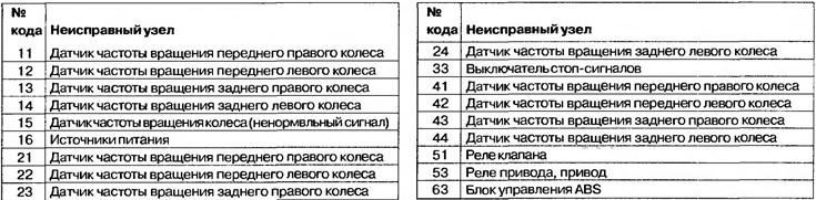
Table 14.5. ABS diagnostic codes
(Original source of information: «MitsubishiMan.ru»)