Examination
1. Install the valve. Press the valve stem against the seat and measure the distance from the end of the stem to the working surface of the valve spring seat (Figure 3.49). If the value is greater than the permissible value, replace the valve seat.
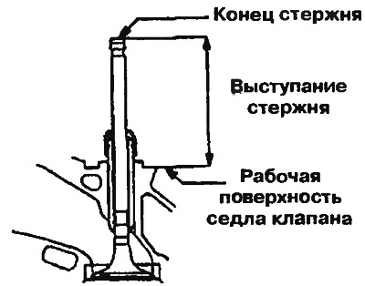
Figure 3.49. Checking the valve seat
| Parameters | Nominal value, mm | Limit value, mm | |
| SOHC 12V | Inlet valve | 43.70 | 44.20 |
| Exhaust valve | 43.30 | 43.80 | |
| SOHC 16V | Inlet valve | 53.21 | 53.71 |
| Exhaust valve | 54.10 | 54.60 | |
| DOHC | Inlet valve | 48.80 | 49.30 |
| Exhaust valve | 48.70 | 49.20 | |
Processing
2. Before machining the valve seat, check the clearance between the valve stem guide and the valve. Replace the valve stem guide if necessary.
3. Using a suitable tool or milling cutter, machine the valve seat to the required valve seat width and angle (Figure 3.50).
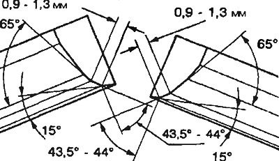
Figure 3.50. Valve seat angles
4. After processing, lap the valve and valve seat with a special lapping paste. Then check the protrusion of the valve stem.
Replacement
5. If the valve seat is removable, pre-treat the inside of the seat with a milling cutter to make it easier to remove. The valve seat can then be replaced with a new one (Figure 3.51).
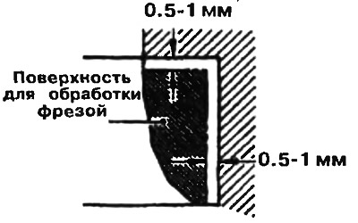
Figure 3.51. To make removing the saddle easier, first cut it with a milling cutter
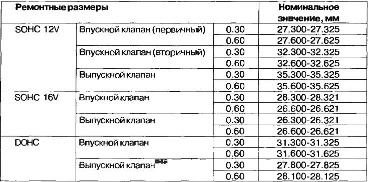
6. Drill a repair size hole for the valve seat in the cylinder head on the outside diameter of the valve seat. The values of the repair sizes of the valve seats are given in Table 3.6.
7. Before installing the valve seat, either heat the cylinder head to 250°C or cool the valve seat with a cooling spray to avoid distortion of the cylinder head bore.
8. Using a valve seat milling cutter, bring the width of the working contact surface and the chamfer angle of the valve seat to the required value.
Table 3.6. Valve seat repair dimensions