



2. Check the piston ring clearance (Figure 3.54). If the value is greater than the permissible value, replace the piston ring, piston, or both parts.
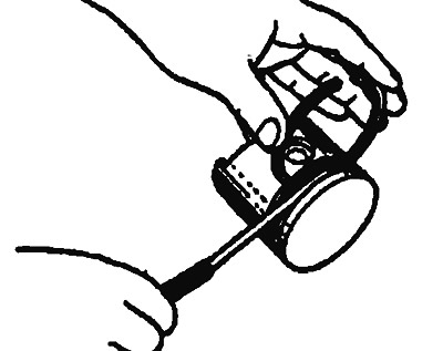
Figure 3.54. Checking the clearance between the piston ring and the piston groove
Normal clearance:
- Upper compression ring: 0.03-0.07 mm.
- Lower compression ring: 0.02-0.06 mm.
Permissible clearance:
- Upper compression ring: 0.1 mm.
- Lower compression ring: 0.1 mm.
| Parameters | Nominal value, mm | Limit value, mm |
| Upper compression ring | 0.20-0.35 | 0.8 |
| Lower compression ring | 0.35-0.50 | 0.8 |
| Oil scraper ring SOHC 12V, DOHC | 0.20-0.50 | 1.0 |
| Oil scraper ring SOHC 16V | 0.10-0.40 | 1.0 |
3. Install the piston ring into the cylinder bore.
4. Press the piston ring with the piston so that it is positioned at a right angle to the inner bore of the cylinder (Figure 3.55). Then measure the gap in the piston ring joint using a gauge.
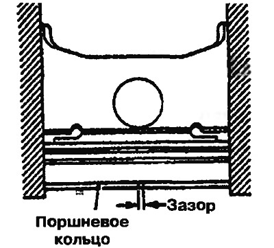
Figure 3.55. Checking the piston ring end clearance
[Information copied from the website: MITSUBISHIMAN.ru]
If the gap is greater than the permissible limit, replace the piston ring.