



Contents: Pulse generator ⤓ Solenoid valves ⤓
Pulse generator
56. Measure the resistance between terminals 1 and 2 or 3 and 4 (Figure 11.165). Nominal resistance: 245 Ohm at 20°C.
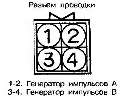
Figure 11.165. Measure the resistance between terminals 1 and 2 or 3 and 4
57. Too little resistance indicates a short circuit, while increased resistance indicates a break in the electrical circuit. In both cases, the pulse generator assembly must be replaced.
Solenoid valves
58. Measure the resistance between the terminal and the body of the individual solenoid valves (Fig. 11.166).
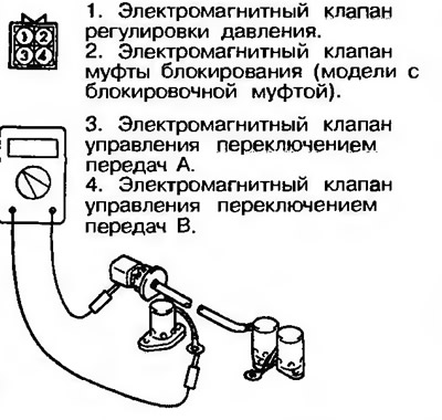
Figure 11.166. Measure the resistance between the terminal and the body of the individual solenoid valves
Nominal resistance:
- electromagnetic pressure control valve - 3 Ohm at 20°C;
- shift control solenoid valve - 22 ohms at 20°C;
- lock-up clutch solenoid valve - 3 ohms at 20°C F4A21, F4A22, F4A23 (models before 1992) and F4A22-2-UPE2-13 ohms at 20'C (models after 1993) (except F4A22-2-UPE2).
59. Too low resistance indicates a short circuit, too high - a break in the electrical circuit. In both cases, the corresponding solenoid valve must be replaced.
60. Connect a 12-volt battery between the terminal and the body of each solenoid valve and check the operating noise (Figure 11.167). The valve is OK if such noise is heard. The absence of noise indicates a stuck or clogged valve. In this case, the valve must be replaced.
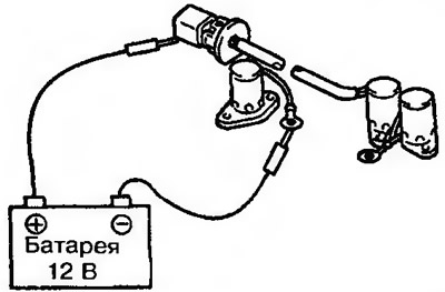
Figure 11.167. Connect a 12-volt battery between the terminal and the body of each solenoid valve and check for operating noise