



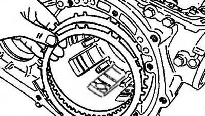
Figure 11.168. Before assembling the gearbox, measure the axial clearance of the load/reverse locking pin and select a pressure plate of such thickness that, after installation, will give the appropriate axial clearance | 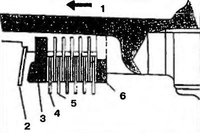
Figure 11.169. Install the brake reaction disc, brake plate and brake disc into the gearbox housing. Install a suitable pressure plate and return spring. 1 - Towards the oil pump; 2 - Return spring; 3 - Pressure plate; 4 - Brake disc; 5 - Brake plate; 6 - Brake reaction disc |
| Box type | Number of brake discs | Number of brake plates |
| F4A21 | 4 | 3 |
| F4A22, F4A23 | 6 | 5 |
62. Apply refined natural petroleum jelly to the shaft spring and secure it to the intermediate support (Figure 11.170). Install the two sealing rings removed during disassembly and lubricate them with ATF transmission fluid.
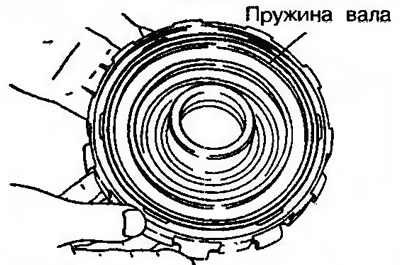
Figure 11.170. Apply refined natural petroleum jelly to the shaft spring and fix it to the intermediate support
63. Install a special tool on the intermediate support and insert it into the gearbox housing (Figure 11.171).
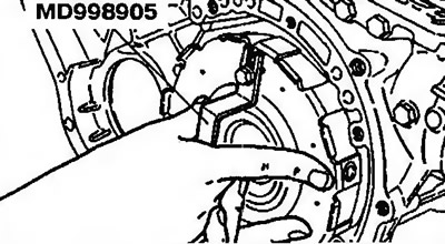
Figure 11.171. Install a special tool on the intermediate support and insert it into the gearbox housing
Caution! When installing the intermediate support, make sure that the shaft spring does not move. Install the intermediate support so that both sealing rings are directed towards the lubrication holes in the gearbox housing.
64. Remove the special tool.
65. Install the snap ring (Figure 11.172).

Figure 11.172. Install the snap ring
66. Install the dial indicator on the back of the gearbox (Figure 11.173). Make sure that the measuring pin MD998913 is inserted into the hole for the intermediate gear shaft and contacts the brake reaction disc (right) in the right corner (Figure 11.174).
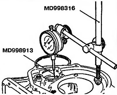
Figure 11.173. Install the dial indicator on the back side of the gearbox | 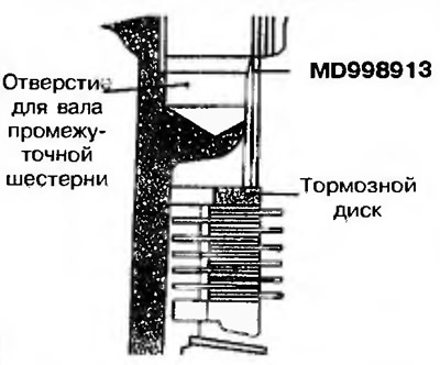
Figure 11.174. Make sure that the MD998913 measuring pin is inserted into the idler shaft hole and contacts the brake disc at the right corner |
67. Using a hand pump, create pressure and note the readings on the dial indicator (Figure 11.175). Based on the measurements obtained, select the pressure plate that provides the required clearance.
Nominal clearance: F4A21 — 0.8-1.0 mm, F4A22, F4A23 — 1.0-1.2 mm.
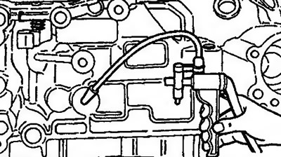
Figure 11.175. Using a hand pump, create pressure and note the readings on the dial gauge
68. After selecting the pressure plate of the appropriate thickness, remove all installed parts.
69. Using a special tool, press in the outer rotating rings (Figure 11.176, 11.177).
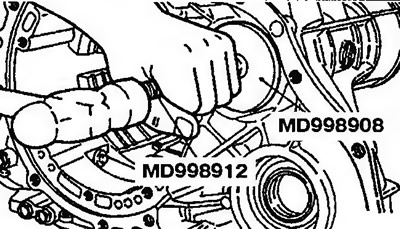
Figure 11.176. Pressing in the outer rotating ring | 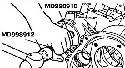
Figure 11.177. Pressing in the outer rotating ring |
70. Install the secondary shaft into the gearbox housing (Figure 11.178).
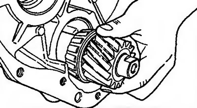
Figure 11.178. Install the secondary shaft into the gearbox housing
71. Install a special tool on the gearbox housing to support the secondary shaft (Figure 11.179).
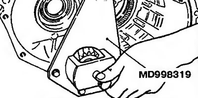
Figure 11.179. Install a special tool on the gearbox housing to support the secondary shaft
72. Install the thickest adjusting washer (1.80 mm) (Figure 11.180).
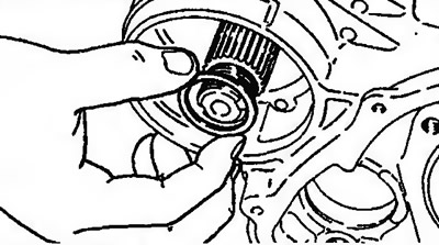
Figure 11.180. Install the thickest adjusting washer (1.80 mm)
73. Install the gear on the secondary shaft (Figure 11.181).
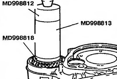
Figure 11.181. Install the gear on the secondary shaft
74. Remove the special tool and secure the secondary shaft (figure 11.159).
75. Install the lock nut and tighten it to the required tightening torque of 200-230 Nm (figure 11.160).
76. Measure the axial clearance by moving the shaft back and forth and select the adjusting shim that provides the required clearance (Figure 11.182). Required clearance; 0-0.025 mm.
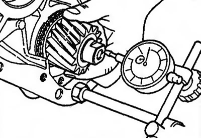
Figure 11.182. Measure the axial clearance by moving the shaft back and forth
77. Bend the lock nut retaining plate (Figure 11.183).
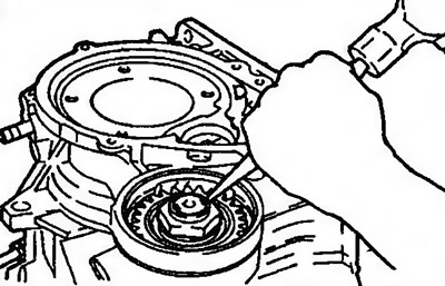
Figure 11.183. Bend the lock nut retaining plate
78. Place the gearbox housing on the workbench with the mounting side of the pan facing up. Insert the secondary shaft flange as a single unit (with two ball bearings and secondary shaft pinion gear installed) into the gearbox housing (figure 11.156).
79. Insert the spring retaining ring (figure 11.155).
80. Apply refined petroleum jelly to the adjusting washer and install it on the gearbox housing (figure 11.154).
81. Insert the outer and inner rotating rings into the intermediate gear (Figure 11.184).
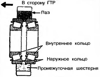
Figure 11.184. Insert the outer and inner rotating rings into the intermediate gear
82. Insert the intermediate gear into the gearbox housing, set the shaft in the appropriate position (figure 11.153).
83. Using a special tool, tighten the intermediate gear shaft (figure 11.152).
84. Install an indicator on the secondary shaft flange and measure the bearing preload (Figure 11.85). Adjust the preload to the required value by tightening or loosening the intermediate gear shaft. Nominal value: automatic transmission F4A21, F4A22 - 0.8 Nm, automatic transmission F4A23 - 1.5 Nm.
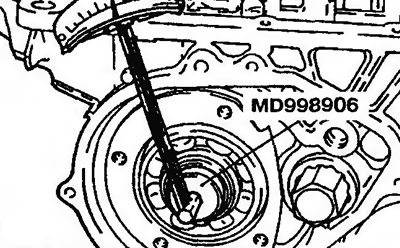
Figure 11.185. Install an indicator on the secondary shaft flange and measure the bearing preload
85. After adjusting the preload, install the intermediate gear shaft lock washer (figure 11.151).
86. Install the bearing bracket and tighten its mounting bolts to a torque of 17-22 Nm (Figure 11.186).
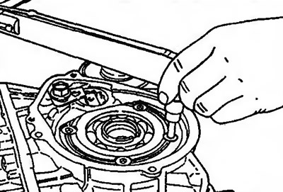
Figure 11.186. Install the bearing bracket and tighten its mounting bolts
87. Using a chisel, fix the bolt head in the appropriate position (Figure 11.187).
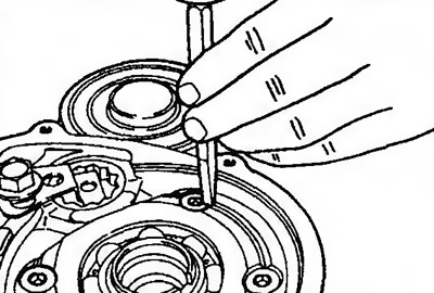
Figure 11.187. Using a chisel, fix the bolt head in the appropriate position
88. Apply to thrust bearing #12 refined petroleum jelly and fix it on the planetary row (Figure 11.188).
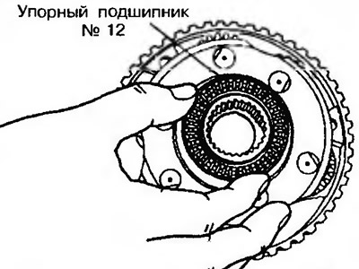
Figure 11.188. Apply refined petroleum jelly to thrust bearing No.12 and fix it on the planetary row
89. Install the planetary gear set into the gearbox housing (Figure 11.189).
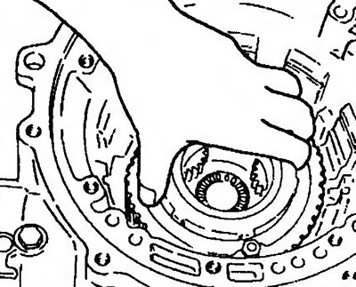
Figure 11.189. Install the planetary gear set into the gearbox housing
90. Install the thrust bearing rotating ring #10thrust bearing #9 onto the forward gear sun gear. Then install the reverse gear sun gear (Figure 11.190).
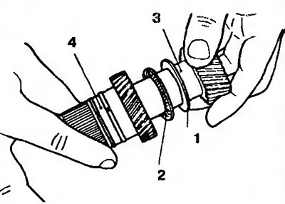
Figure 11.190. Install the thrust bearing rotating ring #10 and thrust bearing #9 onto the forward gear sun gear. Then install the reverse gear sun gear. 1 - Thrust bearing rotating ring #10; 2 - Thrust bearing #9; 3 - Forward gear sun gear; 4 - Reverse gear sun gear
91. Install the sun gear set into the planetary gear set (Figure 11.191).
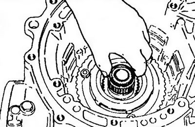
Figure 11.191. Install the sun gear set into the planetary gear set
92. Install the brake discs and plates in the appropriate position (Figure 11.192). The order of the brake discs and plates is shown in Figure 11.169.
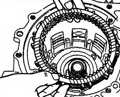
Figure 11.192. Install the brake discs and plates in the appropriate position
93. Install the brake pressure disc selected in accordance with point 61 (Figure 11.193).
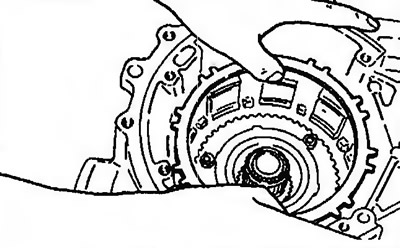
Figure 11.193. Install the brake pressure disc
94. Install the return spring (Figure 11.194).
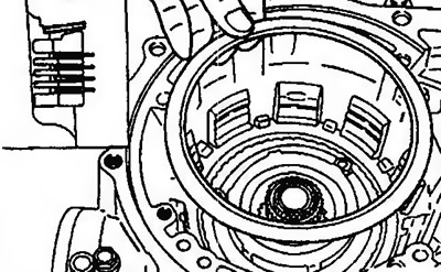
Figure 11.194. Install the return spring
95. Apply refined petroleum jelly to the shaft spring and install it on the intermediate support (Figure 11.170).
96. Install two new sealing rings on the intermediate support (Figure 11.195). Apply ATF transmission fluid to the sealing rings.
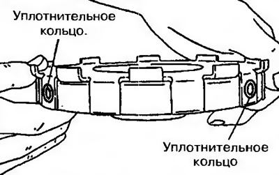
Figure 11.195. Install two new sealing rings on the intermediate support
97. Install a special tool (figure 11.145). Slowly install the intermediate support into the gearbox housing, holding the special tool.
Caution! When installing, make sure that the shaft spring does not fall out. The intermediate support must be installed so that both sealing rings are directed towards the lubrication holes in the gearbox housing.
98. Remove the special tool from the intermediate support.
99. Install the snap ring to secure the intermediate support. The ends of the snap ring must not interfere with the mounting holes of the pulse generator (Figure 11.196).
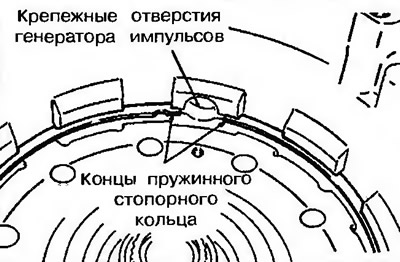
Figure 11.196. Install the snap ring to secure the intermediate support. The ends of the snap ring must not interfere with the mounting holes of the pulse generator
100. Install the rigid mount rod into the gearbox housing (figure 11.143).
101. Install a new Teflon sealing ring and a new oil seal into the grooves of the power steering piston, apply transmission fluid to the ring (Figure 11.197).
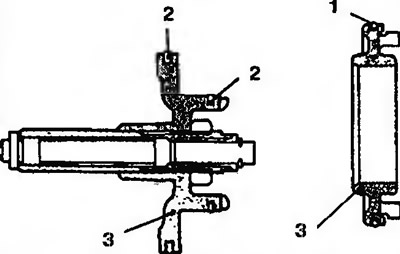
Figure 11.197. Install a new Teflon sealing ring and a new oil seal into the grooves of the power steering piston, apply transmission fluid to the ring. 1 - Sealing ring; 2 - Seal; 3 - Servo amplifier housing
102. Install the servo booster piston into the sleeve.
103. Install the spring on the piston and the servo booster bushing and insert them into the gearbox housing, making sure that the rear slot of the Teflon piston sealing ring does not block the fluid supply hole into the gearbox housing (Figure 11.198).
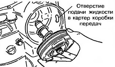
Figure 11.198. Install the spring on the piston and the servo booster bushing and insert them into the gearbox housing, making sure that the rear slot of the Teflon piston seal does not block the fluid supply hole into the gearbox housing
104. Press in the piston and servo booster bushing, then install the snap ring (figure 11.141).
105. Install the brake band so that the arrow points towards the oil pump (F4A23). Connect its ends to the ends of the rigid coupling rod and the servo booster piston rod (Figure 11.199).
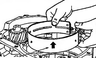
Figure 11.199. Install the brake band so that the arrow points towards the oil pump
106. When installing the brake band into the drum, it is necessary that the keyways of the drum engage with the grooves of the reverse gear sun gear. Install the brake band onto the drum and tighten the adjusting bolt of the brake booster to fix the brake band in the required position (figure 11.139).
107. Apply to thrust bearing #8 refined petroleum jelly and place it on the drum (Figure 11.200).
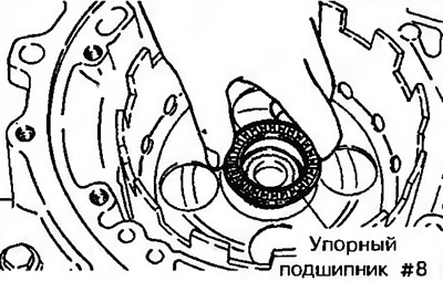
Figure 11.200. Apply to thrust bearing #8 refined vaseline and install it on the drum
108. Apply to the rotating ring of the thrust bearing #7 refined petroleum jelly and install it on the rear hub of the clutch (Figure 11.201).
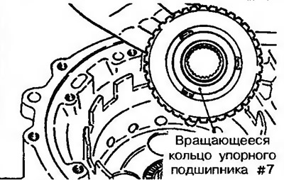
Figure 11.201. Apply to the rotating ring of the thrust bearing #7 refined vaseline and install it on the rear hub of the clutch
109. Install the clutch hub into the keyways of the forward gear sun gear (Figure 11.202).
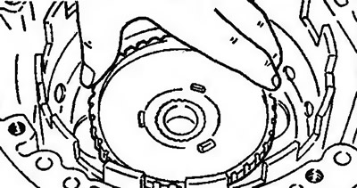
Figure 11.202. Install the clutch hub into the keyways of the forward gear sun gear
110. Apply to thrust bearing #6 refined petroleum jelly and install it on the coupling hub (Figure 11.203).
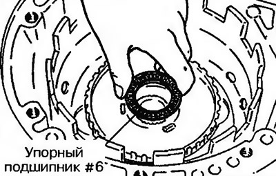
Figure 11.203. Apply to thrust bearing #6 refined vaseline and install it on the clutch hub
111. Apply to the rotating ring of the thrust bearing #2 and on the thrust bearing #4 refined petroleum jelly and install both parts on the rear clutch (Figure 11.204).
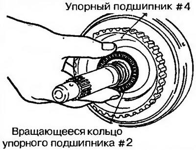
Figure 11.204. Apply to the rotating ring of the thrust bearing #2 and on the thrust bearing #4 refined vaseline and install both parts on the rear clutch
112. Connect the rear and front couplings together (Figure 11.205).
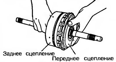
Figure 11.205. Connect the rear and front couplings together
113. Install the clutch assembly into the gearbox housing (figure 11.135).
114. Install the differential (Figure 11.206).
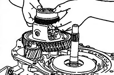
Figure 11.206. Install the differential
115. Install the rotating ring of the thrust bearing on the rear side of the oil pump #3 and adjusting washer #1, having previously lubricated them with refined petroleum jelly (Figure 11.207).
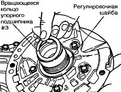
Fig. 11.207. Install the rotating ring of the thrust bearing on the rear side of the oil pump #3 and adjusting washer #1, having previously lubricated them with refined petroleum jelly
116. Install special tool MD998336 onto the gearbox housing. Using special tool MD998336 as a guide, install the oil pump with a new gasket into the gearbox housing (Figure 11.208).
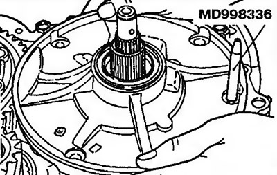
Figure 11.208. Using special tool MD998336 as a guide, install the oil pump with a new gasket into the gearbox housing
117. Remove the special tool.
118. Tighten the oil pump bolts to the specified torque.
119. Measure the axial clearance of the primary shaft (Figure 11.209). If the measured value is outside the permissible limits, replace the rotating ring of the thrust bearing #3 and adjusting washer #1, to obtain the required gap. Required gap: 0.3-1.0 mm.
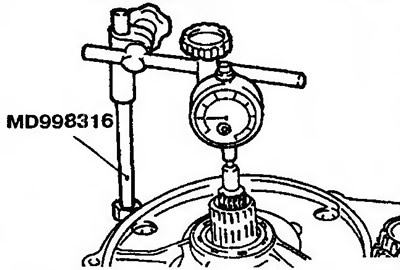
Figure 11.209. Measuring the axial clearance of the primary shaft
120. Apply 10mm long and 1.6mm wide soldering agent to the differential (F4A21, F4A22) (Figure 11.210).
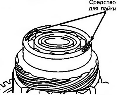
Figure 11.210. Apply 10 mm long and 1.6 mm wide soldering agent to the differential (F4A21, F4A22)
121. Install two pieces of 10 mm long and 1.6 mm diameter soldering wire onto the GTR body and install the outer rotating ring (F4A23) (Figure 11.211).
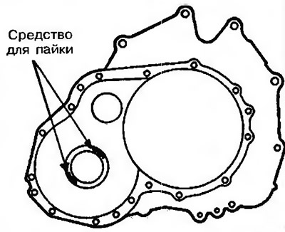
Figure 11.211. Install two pieces of 10 mm long and 1.6 mm diameter soldering wire onto the GTR housing and install the outer rotating ring (F4A23)
122. Install the torque converter housing into the gearbox housing without installing the metal gasket with the rubber layer, and tighten the mounting bolts to the required torque (figure 11.130).
123. Loosen the bolts and remove the GTR housing to remove the soldering agent (F4A21, F4A22).
124. Unscrew the bolts and remove the outer rotating ring from the turbocharger housing. Remove the pressed soldering wire (F4A23).
125. If the wire is not compressed, use a larger diameter wire and repeat steps 122-124.
126. Using a micrometer, measure the thickness of the pressed wire (figure 11.15). Add the measured thickness T to the value 0.38 mm, which corresponds to the thickness of the gasket.
Then subtract the value corresponding to the prescribed axial clearance from the sum. The result obtained corresponds to the thickness of the required adjusting washer.
127. Select a shim whose thickness is within the range calculated using the following formulas:
- Automatic transmission F4A21, F4A22 - from (T +0.38 mm -0.15 mm) to (T +0.38 mm -0 mm).
- Automatic transmission F4A23 - from (T +0.38 mm +0.13 mm) to (T +0.38 mm -0.08 mm).
128. Install the adjusting washer selected in accordance with paragraph 127 on the outer rotating ring of the differential bearing (F4A21, F4A22, F4A23) (Figure 11.212).
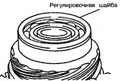
Figure 11.212. Install the adjusting washer on the outer rotating ring of the differential bearing (F4A21, F4A22)
129. Apply silicone grease to all contact surfaces of the gearbox housing (Figure 11.213).
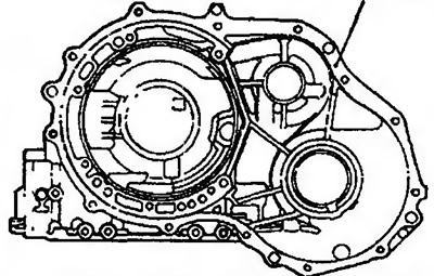
Figure 11.213. Apply silicone grease to all contact surfaces of the gearbox housing
130. Install a new gasket on the gearbox housing.
Caution: Never use a previously removed gasket.
131. Install the torque converter housing and tighten the fourteen bolts to the required torque: 19-23 Nm (figure 11.130).
132. Insert the rear coupling shaft with the side with the longer keyways (figure 11.129).
The original was published on the website www.MitsubishiMan.ru
133. Install the adjusting washer on the end of the return spring on the rear clutch side (Figure 11.214).
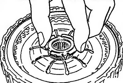
Figure 11.214. Install the adjusting washer on the end of the return spring on the rear clutch side
134. Install the hub on the rear clutch (Figure 11.215),
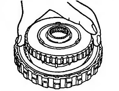
Figure 11.215. Install the hub onto the rear clutch
135. Apply refined petroleum jelly to the thrust bearing #13 and install it on the rear clutch hub (Figure 11.216).
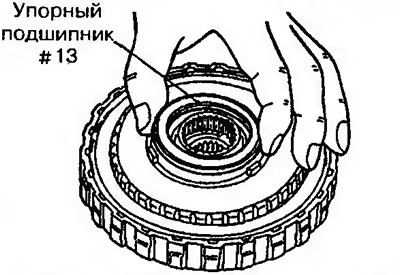
Figure 11.216. Apply refined petroleum jelly to the thrust bearing #13 and install it on the rear clutch hub
136. Install the rear clutch (Figure 11.217).
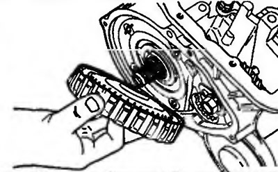
Figure 11.217. Install the rear clutch
137. Install a new sealing ring into the groove of the rear clutch cover (Figure 11.218).
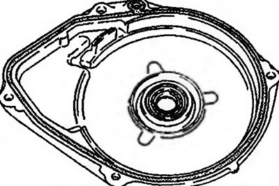
Figure 11.218. Install a new sealing ring into the groove of the rear clutch cover
138. Lubricate the thrust bearing with transmission fluid.
139. Install the rear clutch cover and tighten its mounting bolts to a torque of 6-8 Nm (Figure 11.219).
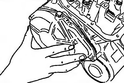
Figure 11.219. Install the rear clutch cover and tighten its mounting bolts
Caution: When installing the rear clutch cover, make sure the threaded holes are centered. Rotating the rear clutch cover may cause the sealing ring to spin.
140. Install the automatic transmission parking lock drive rod onto the gearshift lever shaft. Then insert the shaft into the gearbox housing without pressing the sealing ring into the groove (Figure 11.220).
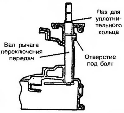
Figure 11.220. Install the automatic transmission parking lock drive rod onto the gearshift lever shaft. Then insert the shaft into the gearbox housing without pressing the sealing ring into the groove
141. Install a new sealing ring onto the gearshift lever shaft and insert the shaft into the gearbox housing, then install the mounting bolt and gasket (figure 11.164a). Insert the steel detent ball, stop and spring (pre-1992 models).
142. Install the locking plate (1993 and later models) (figure 11.164b).
143. Install the gearbox housing with the mounting side of the pan facing up.
144. Install the drive rod support and tighten both bolts to a torque of 20-27 Nm (figure 11.163).
145. Install the sealing ring on the top of the valve block (Figure 11.221).
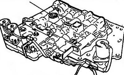
Figure 11.221. Install the sealing ring on the top of the valve block
146. Install a new sealing ring on the solenoid valve connector.
147. When the valve body is installed, connect the solenoid valve connector to the block with its flat end (Figure 11.222).
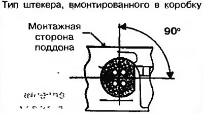
Figure 11.222. Attach the solenoid valve connector to the block with its flat end
148. Insert the wiring harness (arrow) of the electromagnetic valve from the inside through the hole in the gearbox housing (Figure 11.223).
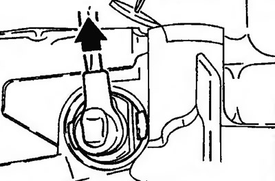
Figure 11.223. Insert the wiring harness (arrow) of the solenoid valve from the inside through the hole in the gearbox housing
149. Install the valve block into the gearbox housing, while simultaneously inserting the locking plate pin into the groove at the end of the valve block (Figure 11.224). Tighten the ten valve block mounting bolts (Figure 11.225a, b). Bolt A - length 18 mm, bolt B - length 25 mm, bolt C - length 40 mm.
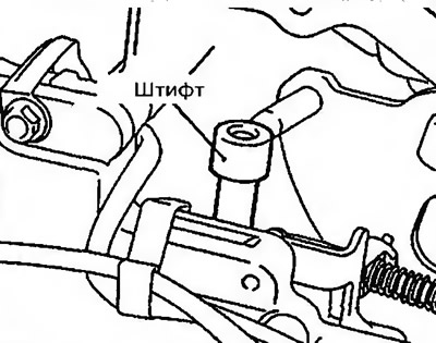
Figure 11.224. Install the valve block into the gearbox housing, while simultaneously inserting the locking plate pin into the groove at the end of the valve block
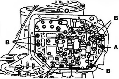
Figure 11.225a. Valve block mounting bolts on models before 1992. | 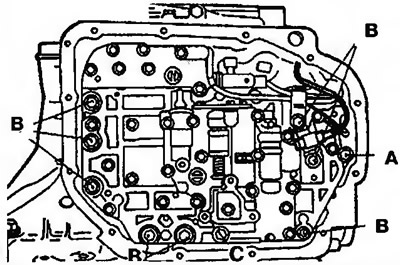
Figure 11.225b. Valve block mounting bolts on models since 1993. |
149. Install the oil filter and tighten the four bolts securing it (Figure 11.226).
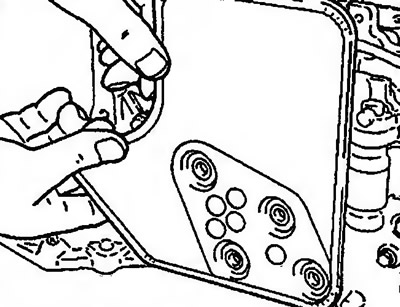
Figure 11.226. Install the oil filter and tighten the four bolts securing it
151. Place five magnets into the five recesses on the inside of the tray (Figure 11.227).
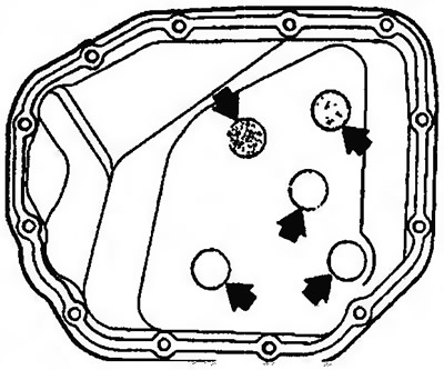
Figure 11.227. Place five magnets in five recesses on the inside of the tray
152. Remove metal particles stuck to the magnets and clean the inside of the oil pan. Clean the contact surfaces of the gearbox housing and the oil pan.
153. Install a new oil pan gasket and tighten the twelve oil pan mounting bolts to a torque of 10-12 Nm (Figure 11.228).
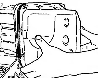
Figure 11.228. Install a new oil pan gasket and tighten the twelve oil pan mounting bolts
154. Adjust the servo amplifier as follows:
- insert the special tool grip into the piston groove so as to prevent the piston from turning and secure it with the adapter (Figure 11.229);
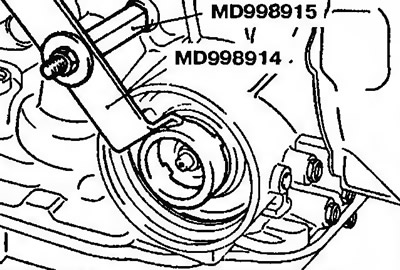
Figure 11.229. Insert the special tool grip into the piston groove so as to prevent the piston from turning and secure it with the adapter
- loosen the lock nut until it almost touches the V-shaped groove in the adjusting rod. Install the special tool MD998916 on the adjusting rod and turn it until it touches the lock nut (Figure 11.230);
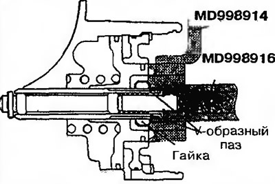
Figure 11.230. Loosen the locknut until it almost touches the V-shaped groove in the adjusting rod. Install the special tool MD998916 on the adjusting rod and rotate it until it touches the locknut
- install the inner special tool on the lock nut (Figure 11.231) Rotate the outer tool counterclockwise and the inner tool clockwise until the lock nut is locked by the inner tool;
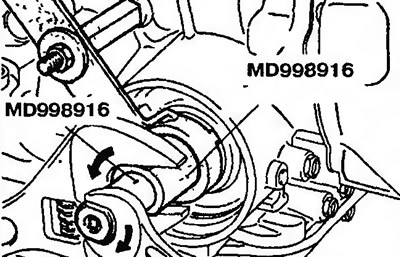
Figure 11.231. Install the inner special tool on the lock nut. Rotate the outer tool counterclockwise and the inner tool clockwise until the lock nut is locked by the inner tool
- attach a torque wrench to the inner tool, tighten it to 10 Nm, and then loosen it again (Figure 11.232). Repeat this procedure twice, and then tighten the inner tool again to 5 Nm. Then loosen the outer tool by 2-2 25 turns;
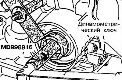
Figure 11.232. Fit a torque wrench to the inner tool, tighten it to 10 Nm, and then loosen it again
- rotate the outer tool clockwise and the inner tool counterclockwise to disengage the inner tool from the lock nut (Figure 11.233);
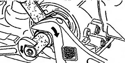
Figure 11.233. Rotate the outer tool clockwise and the inner tool counterclockwise to disengage the inner tool from the lock nut
- tighten the lock nut with your fingers until it touches the piston. Then use a torque wrench to tighten the lock nut to 25-32 Nm (Figure 11.234);
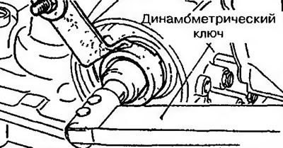
Figure 11.234. Tighten the lock nut with your fingers until it touches the piston. Then tighten the lock nut with a torque wrench
155. Install a new sealing ring on the power steering switch, insert the switch into the gearbox housing and secure it with a spring retaining ring (Figure 11.235a, b).
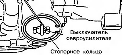
Figure 11.235a. Install a new sealing ring on the power steering switch, insert the switch into the gearbox housing and secure it with a spring retaining ring (models before 1992) | 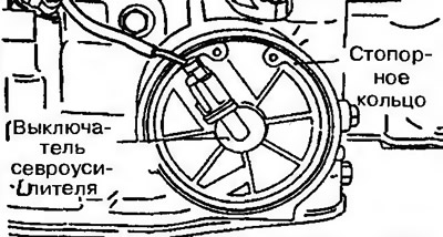
Figure 11.235b. Install a new sealing ring on the power steering switch, insert the switch into the gearbox housing and secure it with a spring retaining ring (models 1993) |
156. Install the starter interlock switch and gear shift lever (Figure 11.236a, b).
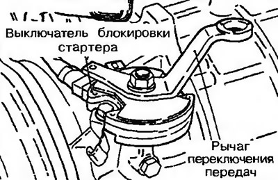
Figure 11.236a. Install the starter interlock switch and gear shift lever (models before 1992) | 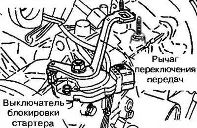
Figure 11.236b. Install the starter interlock switch and gear shift lever (models from 1993) |
157. Adjust the starter interlock switch as follows:
- set the gear shift lever to the "N" position,
- rotate the switch housing until the 12 mm wide end of the gear shift lever aligns with the flange of the switch housing, or rotate the switch housing until the 5 mm hole in the gear shift lever aligns with the same hole in the switch housing (Figure 11.237a,b);
- tighten the mounting bolts to a torque of 10-12 Nm and ensure that the switch does not move.
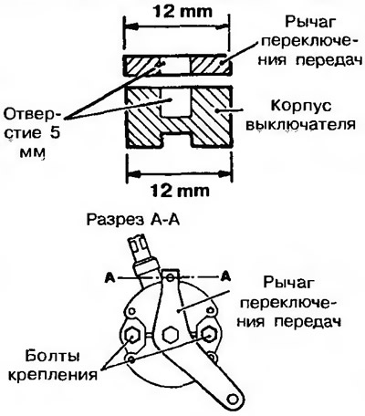
Figure 11.237a. Adjusting the starter interlock switch on models before 1992. | 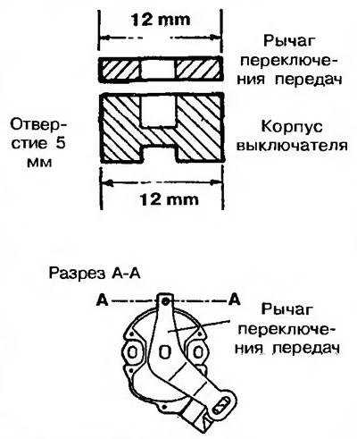
Figure 11.237b. Adjusting the starter interlock switch on models since 1993. |
158. Install pulse generators A and B and tighten the bolts to a torque of 10-12 Nm (Figure 11.238a, b)
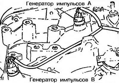
Figure 11.238a. Install pulse generators A and B and tighten their mounting bolts (models before 1992) | 
Figure 11.2386. Install pulse generators A and B and tighten their mounting bolts (models from 1993) |
159. Apply transmission oil to the outside of the cylindrical part of the torque converter facing the oil pump and carefully install the torque converter so as not to damage the working edge of the shaft seal. Check that the torque converter engages with the drive gear of the oil pump.
160. Measure the distance between the toothed ring and the GTR housing. If it is about 12 mm, the transformer is installed correctly (Figure 11.239).
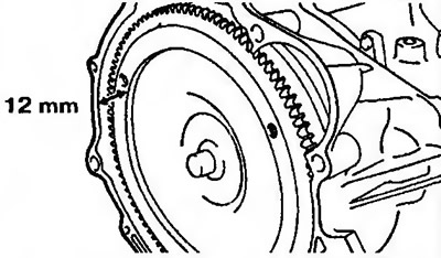
Figure 11.239. Measure the distance between the toothed ring and the GTR housing. If it is about 12 mm, the transformer is installed correctly