
2. Place the box on the workbench with the pallet down.
3. Remove the GTR.
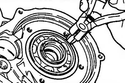
4. Before disassembly, measure the input shaft end play so that you can determine if the shim needs to be changed (this does not apply when important parts are replaced). The shims are located between the reaction shaft support and the clutch rear bracket, and between the reaction shaft support and the clutch front bracket. Mount the dial indicator with the special tool on the transformer housing and place the measuring pointer on the end of the input shaft (pic. 11.115). Press the input shaft with pliers and pull it out to get the end play and write it down.
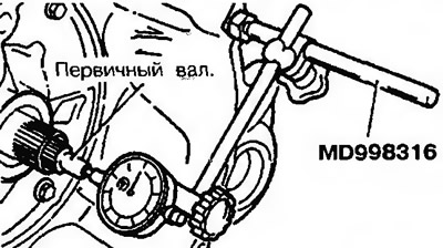
Pic. 11.115. Install the dial indicator with the special tool on the transformer housing and install the measuring pointer on the end of the input shaft.
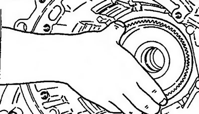
5. Remove pulse generators A and B (pic. 11.116a,b).
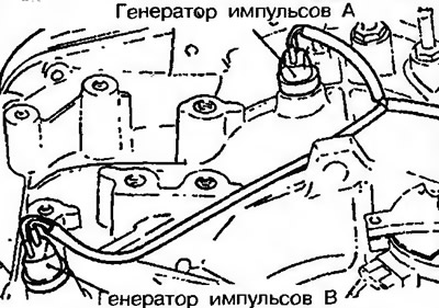
Pic. 11.116a. Remove pulse generators A and B (models until 1992) | 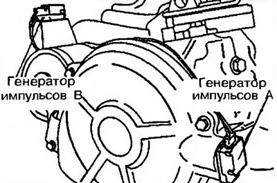
Pic. 11.116b. Remove pulse generators A and B (models since 1993) |
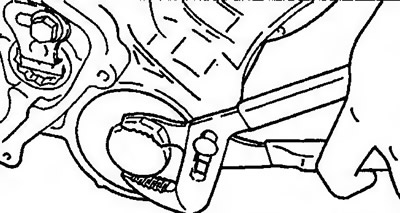
6. Remove shift lever and starter interlock switch (pic. 11.117a,b).
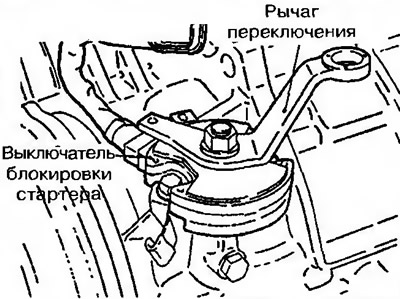
Pic. 11.117a. Remove shift lever and starter interlock switch (models until 1992) | 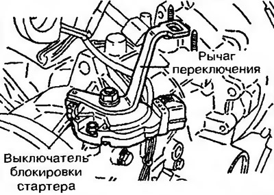
Pic. 11.117b. Remove shift lever and starter interlock switch (models since 1993) |
7. Remove the circlip and servo switch (pic. 11.118a,b).
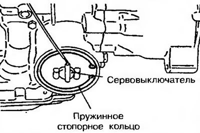
Pic. 11.118a. Remove snap ring and servo switch (models until 1992) | 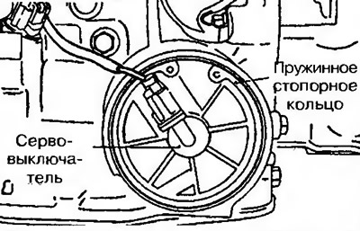
Pic. 11.118b. Remove snap ring and servo switch (models since 1993) |
8. Remove pan and pan gasket (pic. 11.119).
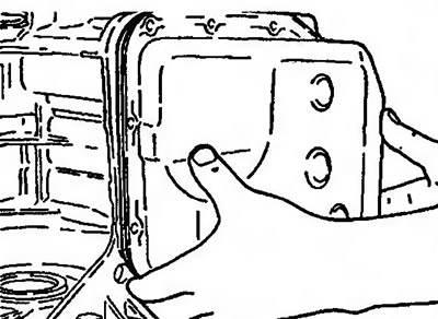
Pic. 11.119. Remove pan and pan gasket
9. Remove the oil filter (pic. 11.120).
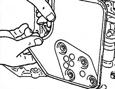
Pic. 11.120. Remove the oil filter
10. Turn off bolts of fastening of the gauge of temperature of oil (pic. 11.121a,b). Using a screwdriver, push out the rubber bushing from the inside of the housing and remove the oil temperature sensor from the housing.
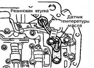
Pic. 11.121a. Loosen the oil temperature sensor mounting bolts (models until 1992) | 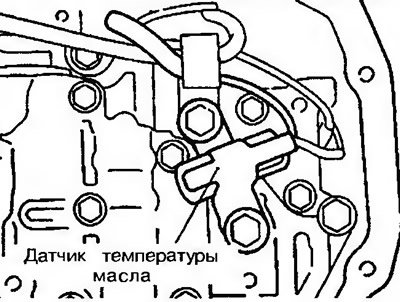
Pic. 11.121b. Loosen the oil temperature sensor mounting bolts (models since 1993) |
11. Remove clip from solenoid valve wiring connector (pic. 11.122).
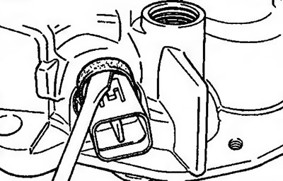
Pic. 11.122. Remove the clamp from the solenoid valve wiring connector
12. Squeeze the latches and press the tip of the wiring harness and the wiring connector into the gearbox housing (pic. 11.123).
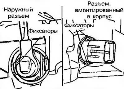
Pic. 11.123. Squeeze the latches and press the wire harness tip and wiring connector into the gearbox housing
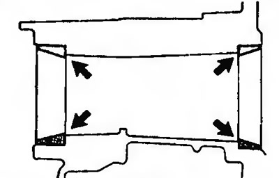
13. Unscrew the bolts of the valve block, indicated by arrows, and remove the valve block from the gearbox housing (pic. 11.124a,b).
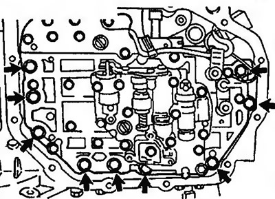
Pic. 11.124a. Unscrew the bolts of the valve block, marked with arrows (models until 1992) | 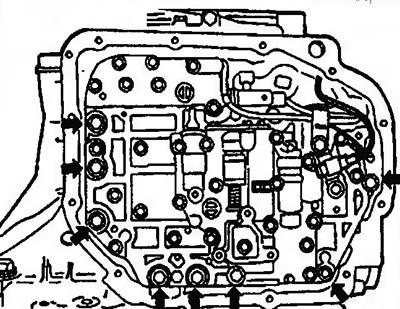
Pic. 11.1246. Unscrew the bolts of the valve block, marked with arrows (models since 1993) |
14. Remove rear clutch cover (pic. 11.125).
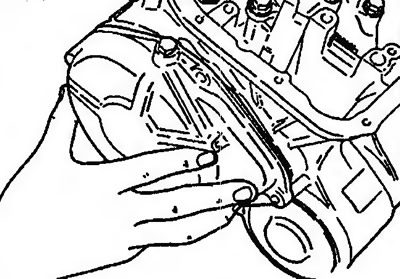
Pic. 11.125. Remove rear clutch cover
15. Remove rear clutch (pic. 11.126).
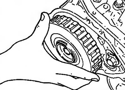
Pic. 11.126. Remove rear clutch
16. Remove the shim from the end of the input shaft (pic. 11.127).
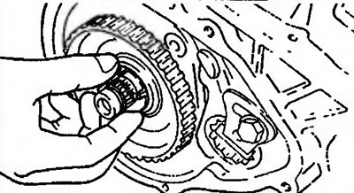
Pic. 11.127. Remove the shim from the end of the input shaft
17. Remove the rear clutch hub and thrust bearing (pic. 11.128).
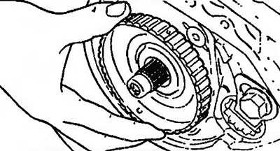
Pic. 11.128. Remove the rear clutch hub and thrust bearing
18. Remove the rear clutch shaft (pic. 11.129).
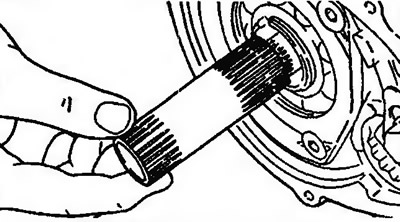
Pic. 11.129. Remove the rear clutch shaft
19. Unscrew the fourteen bolts and remove the GTR body and gasket (rice, 11.130).
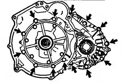
Pic. 11.130. Remove the fourteen bolts and remove the GTR body and gasket
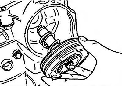
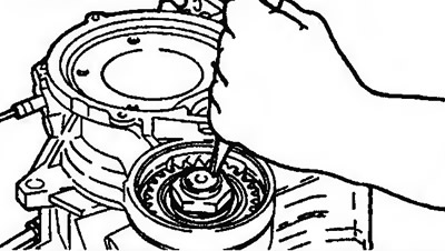
20. Turn off six bolts of fastening of the oil pump (pic. 11.131).
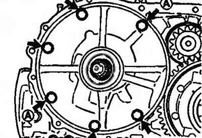
Pic. 11.131. Loosen the six oil pump mounting bolts
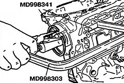
21. Screw special tools MD998333 into hole A.
22. Fix the special tools MD998333 and remove the oil pump (pic. 11.132). Then remove the gasket.
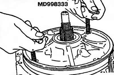
Pic. 11.132. Fix the special tools MD998333 and remove the oil pump
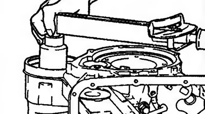
23. Remove the adjusting washer from the automatic transmission case and remove the differential (rice, 11.133).
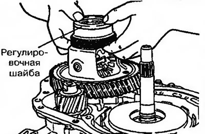
Pic. 11.133. Remove the adjusting washer from the automatic transmission case and remove the differential
24. Remove the plastic shim (pic. 11.134).
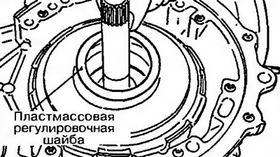
Pic. 11.134. Remove the plastic shim
25. Attach the input shaft and lift it up so that the front and rear clutch kits can be removed (pic. 11.135).
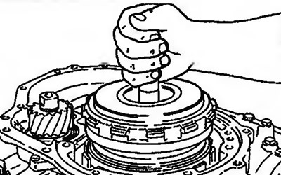
Pic. 11.135. Secure the input shaft and lift it up so that the front and rear clutch kits can be removed
26. Remove thrust bearing (pic. 11.136).
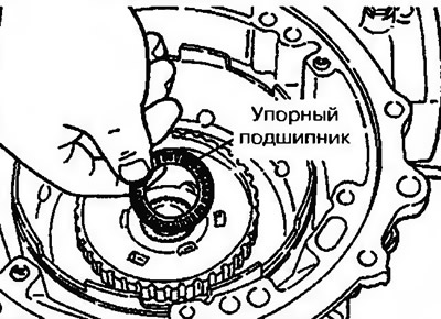
Pic. 11.136. Remove thrust bearing
27. Remove the clutch hub (pic. 11.137).

Pic. 11.137. Remove the clutch hub
28. Remove the thrust bearing rotating race (from below) and thrust bearing (above (pic. 11.138).
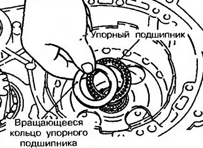
Pic. 11.138. Remove the thrust bearing rotating race and thrust bearing
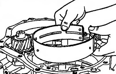
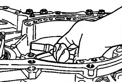
29. Remove the brake drum (pic. 11.139).
Pic. 11.139. Remove the brake drum
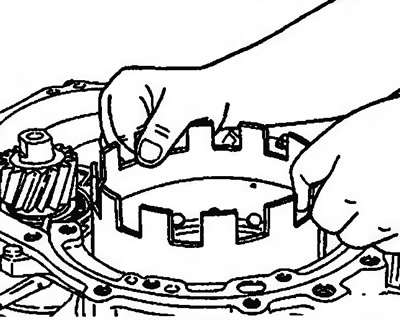
30. Remove the brake band (pic. 11.140).
Pic. 11.140. Remove the brake band
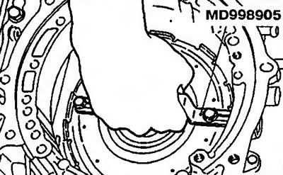
31. Using the special tool, compress the servo and remove the circlip (pic. 11.141).
Pic. 11.141. Using the special tool, compress the servo and remove the circlip
32. Remove the special tool, and then remove the piston, bushing and servo spring (pic. 11.142).
Pic. 11.142. Remove the special tool and then remove the piston, bushing and servo spring
33. Remove the hard mount rod (pic. 11.143).
Pic. 11.143. Remove the hard mount
34. Remove the circlip (pic. 11.144).
Pic. 11.144. Remove snap ring
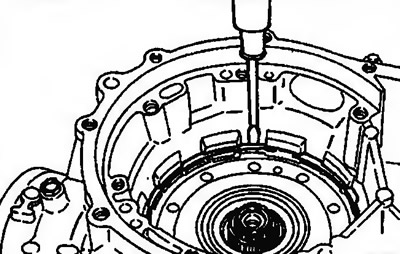
35. Install the special tool on the intermediate support and remove it from the crankcase (pic. 11.145).
Pic. 11.145. Install the special tool on the intermediate support and remove it from the crankcase
36. Remove the forward and reverse sun gears along with the #9 thrust bearing and #10 thrust bearing rotating race (pic. 11.146).
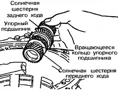
Pic. 11.146. Remove the forward and reverse sun gears along with the #9 thrust bearing and #10 thrust bearing rotating race
37. Remove planetary gear set and thrust bearing #12 (pic. 11.147).
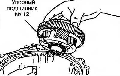
Pic. 11.147. Remove planetary gear and thrust bearing
38. Remove shaft spring, return spring, reaction discs, brake discs and friction plates (pic. 11.148).
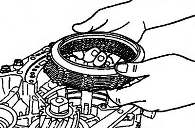
Pic. 11.148. Remove the shaft spring, return spring, reaction discs, brake discs and friction plates
39. Apply sealant to the bearing bracket bolts. Tap the bolt heads lightly to make them easier to unscrew (pic. 11.149).
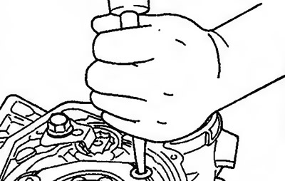
Pic. 11.149. Apply sealant to the bearing bracket bolts. Tap the bolt heads lightly to make them easier to unscrew
40. Using a screwdriver, unscrew the bolts and remove the bearing bracket (pic. 11.150).
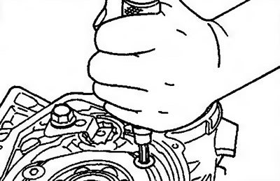
Pic. 11.150. Using a screwdriver, unscrew the bolts and remove the bearing bracket
41. Remove the idler shaft lock washer (pic. 11.151).
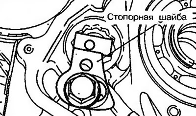
Pic. 11.151. Remove the intermediate gear shaft lock washer
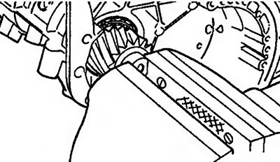
42. Loosen the idler shaft with the special tool (pic. 11.152).
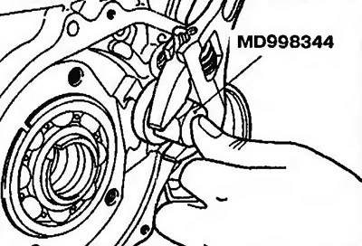
Pic. 11.152. Loosen the intermediate gear shaft with the special tool
43. Remove the idler shaft, then remove the idler gear and two inner bearing races (pic. 11.153).
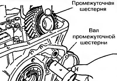
Pic. 11.153. Remove the idler shaft, then remove the idler gear and two bearing inner races
44. Remove the shim (fig.11.154).
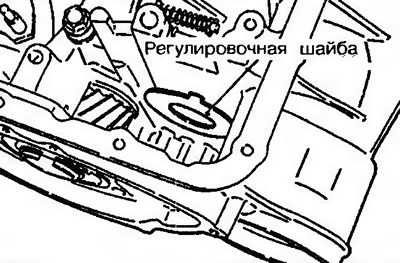
Pic. 11.154. Remove the adjusting washer
45. Remove the circlip from the output shaft mounting flange (pic. 11.155).
Pic. 11.155. Remove the circlip from the output shaft mounting flange
46. Remove the output shaft flange from the crankcase (pic. 11.156).
Pic. 11.156. Remove the output shaft flange from the crankcase
47. Remove the output shaft cover (pic. 11.157).
Rice, 11.157. Remove the output shaft cover
48. Straighten the retaining plates of the output shaft locknut (pic. 11.158).
Pic. 11.158. Straighten the retaining plates of the output shaft locknut
49. Fix the secondary shaft in the GTR housing (pic. 11.159).
Pic. 11.159. Fix the output shaft in the GTR housing
50. Unscrew the locknut (pic. 11.160).
Pic. 11.160. Loosen the locknut
Attention! This nut is left hand threaded.
51. Press the output shaft towards the GTR body and remove the output shaft and gear (pic. 11.161).
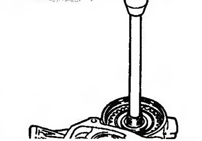
Fig.11.161. Press the output shaft towards the GTR housing and remove the shaft and output shaft gear
52. Remove the outer rotating ring of the output shaft bearings (pic. 11.162).
Pic. 11.162. Remove the outer rotating ring of the output shaft bearing
53. Remove drive link support (only on models up to 1992 onwards.) (pic. 11.163).
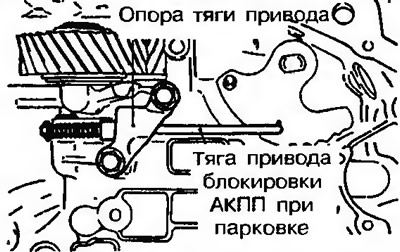
Pic. 11.163. Remove drive link support (only on models up to 1992 onwards.)
54. Remove the set bolt and shift lever shaft, then remove the steel ball, stop and spring (only on models up to 1992.) (pic. 11.164a).
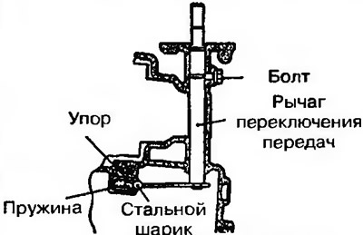
Pic. 11.164a. Remove the set bolt and shift lever shaft, then remove the steel ball, stop and spring (only on models up to 1992 onwards.)
55. Remove the set bolt and drive link support, as well as the shift lever shaft and detent plate (only on models from 1993 onwards.) (pic. 11.164b).
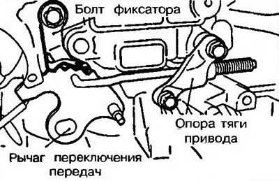
Pic. 11.1646. Remove the set bolt and drive link support, as well as the shift lever shaft and detent plate (only on models from 1993 onwards.)