English Русский
Български
Беларускі
Український
Српски
Hrvatski
Română
Polski
Slovenský
Magyar
Articles Bookmark Contacts Sitemap   
Company Audi Company Ford Company Hyundai Company Kia Company Mazda Company Mercedes-Benz Company Nissan
MitsubishiMan.ru


Home Colt Lancer Galant L200 Outlander Pajero Others
Galant 6 and 7 (1987-1998) Galant 5 (1983-1989, petrol)

Removal and installation the ignition distributor (with contactless ignition system) (Mitsubishi Galant 6)

  • Home
  • Galant
  • 6 (1987-1998)
  • Power unit
  • Engine electrical equipment
  • Removal and installation the ignition distributor (with contactless ignition system)
0
Contents: Removal ⤓ Installation ⤓

Removal


1. Bring the engine to the TDC position of the end of the compression stroke of the piston of the first cylinder, - be guided by the installation marks of the timing drive gears (see Chapter Engine).

2. Disconnect the negative cable from the battery.

Warning! If the car stereo system is equipped with a security code, make sure you have the correct combination to activate the audio system before disconnecting the battery!


3. If equipped, remove the protective cover of the high-voltage wiring harness.

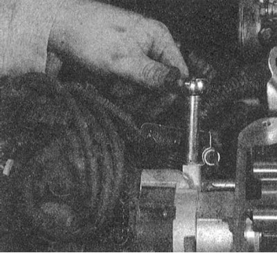
4. Disconnect the electrical wiring from the distributor, loosen the mounting bolt and move the electrical wiring harness with the capacitor connected to it to the side.
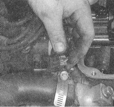

5. Remove the distributor cap with the high-voltage wires connected to it.

6. If necessary, disconnect the coil wire.

7. Mark the position of the runner relative to the distributor housing and the position of the housing relative to the engine.
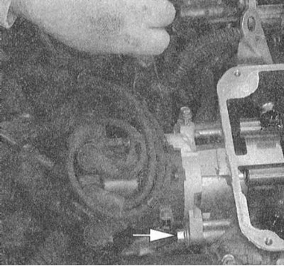


8. Remove the clamping nut.
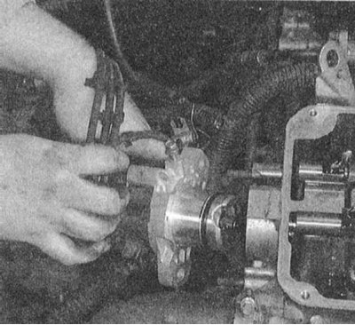


9. Carefully remove the distributor from the engine.

Installation


The timing marks are aligned (the engine has not been turned)


1. After lightly lubricating with clean machine oil, install a new O-ring onto the distributor.

2. Install the distributor on the engine - make sure that the mounting marks (housing and runner) are aligned correctly. Make sure that the distributor is fully seated and that its drive shaft is engaged.

3. Screw on the clamping nut.

4. Connect the electrical wiring to the distributor and secure the harness with a special bolt.

5. Install the cover with the high-voltage wires connected to it on the distributor.

6. Connect the negative cable to the battery.

7. Adjust the ignition timing (see Section Checking/adjusting the ignition timing), then finally tighten the clamping nut to the required torque (11 Nm).

The timing marks are misaligned (the engine was turned over with the distributor removed)


1. Install a new sealing ring on the distributor.
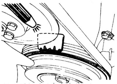


2. Bring the engine to the TDC position of the end of the compression stroke of the first cylinder - be guided by the alignment of the timing marks of the timing drive gears (see Chapter Engine). Also make sure that the mark on the vibration damper is opposite the zero mark on the dial gauge.

3. Having checked the correct alignment of the mounting marks applied during the dismantling of the components, install the distributor on the engine - the guide pin should fit into the mating groove of the mounting flange. Make sure that the assembly is completely seated and that the runner is turned with its nose towards the location of the first cylinder terminal on the cover (a mounting mark was applied to the rim of the housing during dismantling).
This article is available at: russian, bulgarian, belarusian, ukrainian, serbian, croatian, romanian, polish, slovak, hungarian
This article was reviewed by: Dmitry Vasiliev
Share with friends:
◀ Previous
Galant 6 and 7: Engine electrical equipment
Next ▶

Removal and installation the key transistor (ignition module)
Checking the condition and replacing the ignition coil
Checking and adjusting the ignition system
Ignition System — General Information and Precautions
Checking the condition and replacing battery wires
Firing order
Charging system — general information and precautions
Checking the status of the charging system
Checking, removing and installing the generator
Starting System — General Information and Precautions
Similar materials for other Mitsubishi models

➤ Ignition system elements without distributor — removal and… Mitsubishi Colt 4 and 5 (1991-2003)
➤ Ignition distributor — device Mitsubishi Lancer 3 and 5 (1984-1992)
➤ Ignition switch Mitsubishi L200 4 (2005-2014, diesel)
➤ Electrical diagram of the ignition system Mitsubishi Outlander 1 (2003-2008)
➤ Design and description of the ignition system Mitsubishi Pajero 1 and 2 (1982-1999)
➤ Scheme 1. Ignition system MPI-SOHC Mitsubishi Carisma (1995-2004)
Link in different formats to this article
Comments and feedback from visitors
No comments yet


Add up two numbers 46 + 44


Galant 6 and 7 (1987-1998) 
  • General information
  • Introduction to guide
  • User manual
  • Driving and operation
  • Maintenance
  • Power unit
  • Dismantling the engine
  • Engine overhaul
  • Cooling and heating
  • Power and exhaust systems
  • Engine electrical equipment
  • Engine management systems
  • Transmission
  • Mechanical gearbox
  • Automatic gearbox
  • Clutch
  • Drive shafts and transfer case
  • Chassis and running gear
  • Brake system
  • Car suspension
  • Steering
  • Body and interior
  • Exterior (external elements)
  • Interior (internal elements)
  • Doors, locks and windows
  • Electrical equipment
  • Equipment and devices
  • Wiring diagrams Galant
  • Wiring diagrams Mirage
  • Wiring diagrams Diamante
Galant 5 (1983-1989, petrol) 
  • General information
  • Troubleshooting
  • Maintenance
  • Power unit
  • Engine repair
  • Engine overhaul
  • Cooling and heating
  • Fuel and exhaust system
  • Engine electrical equipment
  • Reducing exhaust toxicity
  • Transmission
  • Manual gearbox
  • Automatic gearbox
  • Clutch and drive shafts
  • Chassis and running gear
  • Brake system
  • Car suspension
  • Steering
  • Body and interior
  • Exterior (external elements)
  • Interior (internal elements)
  • Doors, locks and windows
  • Electrical equipment
  • Equipment and devices
  • Electrical diagrams
MitsubishiMan.ru © 2018–2026 • Mobile version • Articles about Mitsubishi • Contacts • Sitemap: EN BG BY UA RS HR RO PL SK HU • Site search • Bookmark
Colt 2 and 3 (1983-1993) · Colt 4 and 5 (1991-2003) · Colt 5 (1995-2003) · Lancer 3 and 5 (1984-1992) · Lancer 9 (2000-2007) · Galant 5 (1983-1989) · Galant 6 and 7 (1987-1998) · L200 4 (2005-2014) · Outlander 1 (2003-2008) · Pajero 1 and 2 (1982-1999) · Pajero 4 (2006-2021) · Carisma (1995-2004) · Space Star (1998-2005) ·
This resource sets cookies 🍪 to avoid bothering you with repeated data entry.