
Details of the clutch and release mechanism (hydraulic drive)
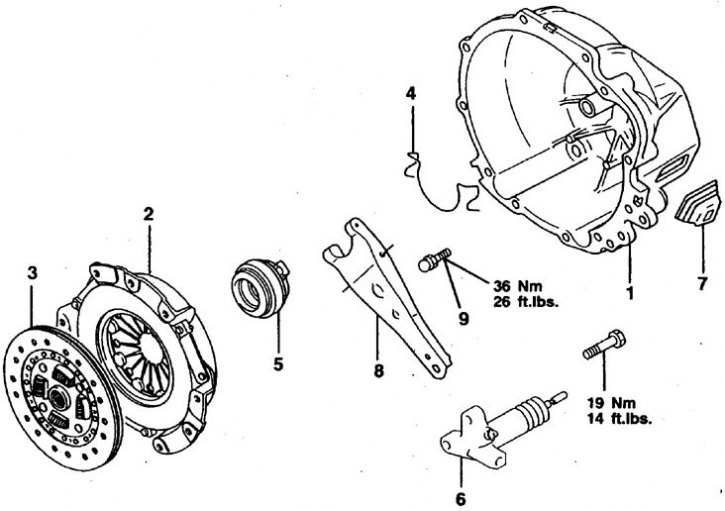
1. Gearbox; 2. Cover of a conducted disk; 3. Friction disc; 4. Fork spring; 5. Release bearing; 6. Working cylinder; 7. Case; 8. Fork; 9. Hinge
Clutch line
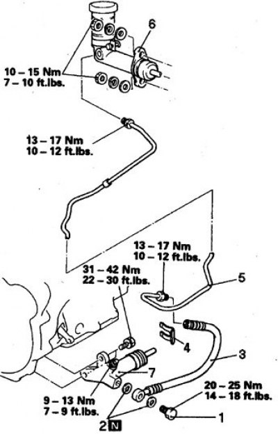
1. Bolt union fitting; 2. Gasket; 3. Hose; 4. Bracket; 5. Tube; 6. Master cylinder; 7. Working cylinder
Hydraulic hoses and tube
This procedure applies to both vehicles with and without ABS.
1. Raise the vehicle.
2. Substitute the vessel, unscrew the bolt of the union fitting on the clutch slave cylinder and drain the fluid from the hydraulic drive.
3. Turn away a nut of the union of a tube and remove a hose.
4. If necessary, remove the ABS system connector.
5. Installation is carried out in the reverse order.
6. Tighten all connections to the required torque.
7. Fill fluid and bleed hydraulic fluid.
Fork and release bearing
1. Remove the gearbox (see subsection 9.1.6).
2. Remove the return spring and release bearing.
3. Remove the master cylinder from the gearbox housing.
4. Remove the clutch release fork cover.
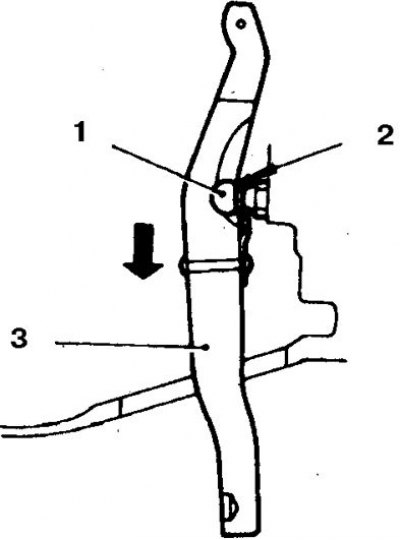
5. Remove the plug (3) with hinge (1), shifting it towards the hole in the crankcase and releasing the spring clip (2). To avoid damage, do not remove the plug in any other way.
6. If necessary, unscrew the fork pivot.
7. Installation is carried out in the reverse order.
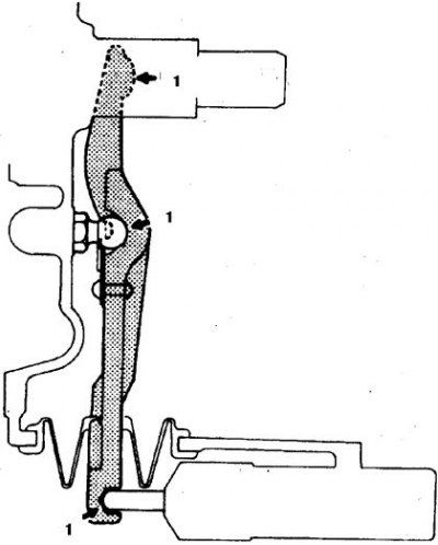
8. Lubricate friction surfaces (1) fork, rod of the working cylinder and hinge.