



Contents: Removal ⤓ Checking the door lock drive ⤓ Checking the door lock cylinder ⤓ Checking the left door lock cylinder ⤓ Checking the right door lock cylinder ⤓ Installation ⤓
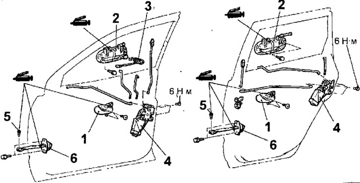
Fig. 17.50. Door lock and handle: 1 - inner door handle; 2 - outer door handle; 3 - front door lock cylinder; 4 - lock lock drive; 5 - door lock assembly; 5-spring cylindrical pin; 6 - door opening limiter
Removal
- Disconnect the cable from the negative battery terminal.
- Remove the upholstery and dust and moisture protection film from the door.
- Remove the self-tapping screws and remove the inner door opening handle.
- Disconnect the rod from the front door lock handle.
- Remove the bolt and the outer door handle.
- Remove the front door lock cylinder.
- Remove 3 screws and remove the door lock assembly.
- If necessary, remove the electronic control unit of the door locking system (vehicles with central door locking) (Fig. 17.51).
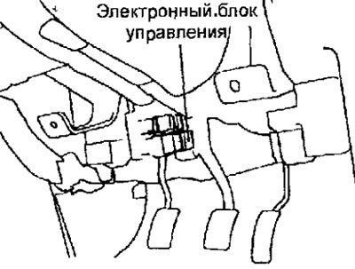
Fig. 17.51. Location of the electronic control unit for the door locking system
Checking the door lock drive
- Make sure that when voltage is applied from the positive terminal of the battery to contact 1 of the drive connector and from the negative terminal to contact 2, the drive switches from the locking mode to the unlocking mode (Fig. 17.52). When the polarity of the voltage applied to the connector contacts changes, the drive switches from the unlocking mode to the locking mode.
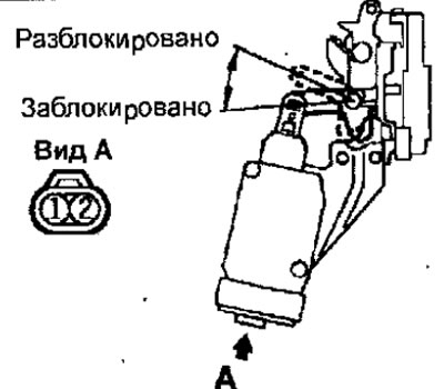
Fig. 17.52. Checking the door lock drive
Checking the door lock cylinder
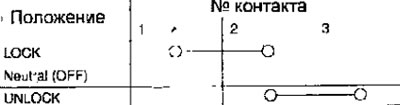
- Use an ohmmeter to measure the conductivity between the connector contacts in different positions of the door lock cylinder.
Checking the left door lock cylinder
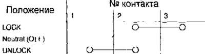
Checking the right door lock cylinder
Installation
- Installation is carried out in the reverse order of removal, taking into account the following.
- Check the stroke of the inner door handle.
- Install the door trim.
- Adjust the door position.