



Contents: Removal ⤓ Installation ⤓
Removal
- Remove the upholstery and dust and moisture protection film from the door.
- Remove the outside rearview mirror from the front door.
- Remove the inner door glass seal.
- Lower the glass and remove the glass guide seal.
- Remove the screws and remove the guide channel from the rear door (Fig. 17.37).
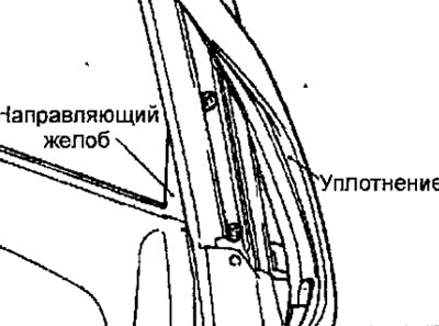
Fig. 17.37. Removing the guide channel from the rear door
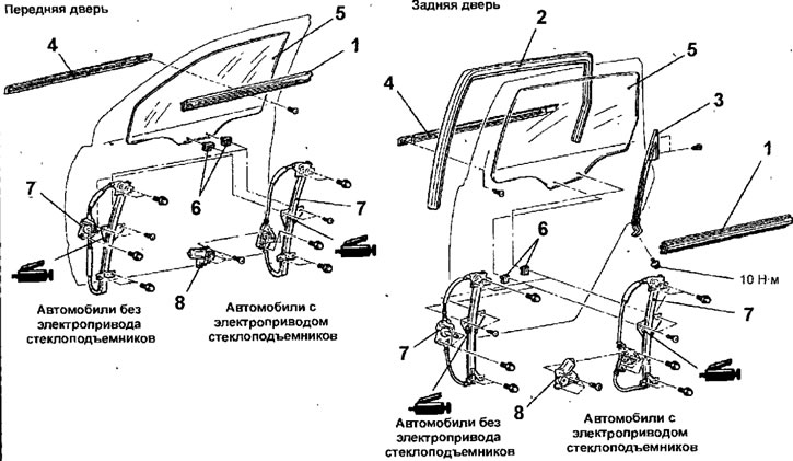
Fig. 17.38. Door glass and window lifter: 1 - inner door glass seal; 2 - glass guide seal; 3 - guide chute; 4 - inner door glass seal; 5 - glass; 6 - glass holder; 7 - window lifter; 8 - electric window lifter.
- From the inside of the door, remove the inner door glass seal.
- Through the holes in the inner door panel, unscrew the screws securing the window regulator to the glass holders.
- Use adhesive tape to secure the glass to the door.
- Disconnect the window motor electrical connector from the door wiring harness.
- Remove the bolts and pull the window regulator out through the holes in the inner door panel.
Warning: Use caution when removing the window regulator as the compressed spring may cause the cable to come off the window regulator drum.
- If necessary, remove the bolts and window lift motor.
- Remove the glass from the door by tilting it forward and lifting it up.
Installation
- Installation is carried out in the reverse order of removal, taking into account the following.
- If the splines in the window lift mechanism drum and on the electric window lift drive do not align, move the glass bracket and turn the drum in the window lift mechanism to a position in which the splines in the window lift mechanism drum and on the electric window lift drive align (Fig. 17.39, 17.40).
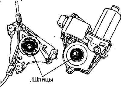
Fig. 17.39. Alignment of splines in the window lift mechanism drum and on the electric window lift drive
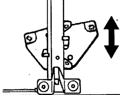
Fig. 17.40. Directions of movement of the glass bracket for turning the drum of the window lift mechanism
- Position the drum, window regulator guide and window regulator drive in the work area as shown in Figure 17.41.
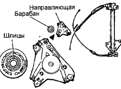
Fig. 17.41. Location of drum, window lift guide and window lift drive
(Original version of the article on the website: MitsubishiMan.ru)
(1) Position the window regulator guide so that the cable grooves face upward.
(2) Position the window regulator guide so that the glass bracket is at the bottom. Move the glass bracket to the fully open position.
- Install the springs on the cables. Then install the lowering cable into the window lift guide first, then the lifting cable (Fig. 17.42).
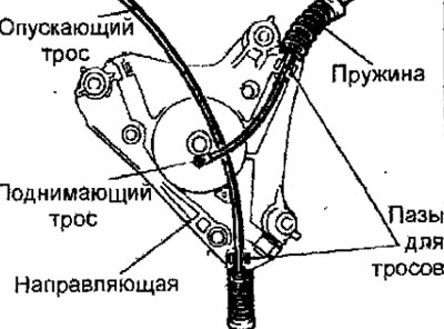
Fig. 17.42. Installing the lifting and lowering cables into the window lift guide
- The lifting cable must be located above the lowering cable.
- Compress the springs and tie them together with thin wire (Fig. 17.43).
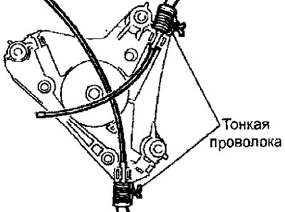
Fig. 17.43. Using thin wire to tie springs
Note: The thin wire must be placed in the grooves for the cables.
- Insert the end of the lowering rope into the hole located at the base of the drum, then wrap the rope securely around the recess of the drum so that there is no gap between the rope and the drum (Fig. 17.44).
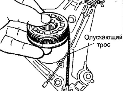
Fig. 17.44. Winding the lowering rope onto the drum
- Attach the lifting cable to the drum as follows:
(1) Insert the tip of the lifting cable into the hole located at the top of the drum (Fig. 17.45).
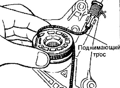
Fig. 17.45. Installing the lifting cable into the drum
(2) Raise the front of the drum until it is in a vertical position, then insert the lifting cable into the groove of the drum (Fig. 17.46).
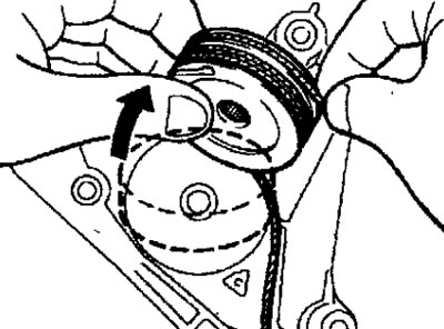
Fig. 17.46. Installing the lifting cable into the drum groove
(3) Turn the drum back to its original position, holding the cables so that they do not slip off the drum (Fig. 17.47).
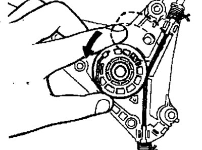
Fig. 17.47. Rotating the drum to its original position
- After installing the window lift motor onto the window lifter, cut and remove the wire that connects the springs.
- Install the window regulator into the door and secure with bolts.
- Temporarily attach the glass to the window regulator.
- After the glass has been fully raised, finally tighten the bolts securing the glass to the window regulator bracket.
Note: When the door glass is fully raised, the limit switch is automatically set to the correct position.