



Contents: Removal ⤓ Installation ⤓
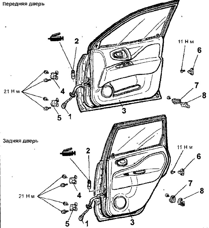
Fig. 17.26. Doors: 1 - wiring harness connector; 2- door opening limiter split pin; 3 - door assembly; 4 - upper door hinge; 5 - lower door hinge; 6 - lock retainer; 7 - retainer gasket; 8 - door limit switch cover; 9 - door limit switch
Removal
- Open the door and support it with stands or jacks, placing a clean rag between them and the door.
- Disconnect the electrical connector of the wiring harness from the mirror, windows and central locking.
- Unscrew the door opening limiter mounting bolts.
- Use a marker to mark the position of the door hinges.
- While an assistant supports the door, remove the door hinge bolts and remove the door from the vehicle.
- Use a marker to mark the position of the lock retainer and remove the bolts securing the lock retainer to the front or middle pillar of the vehicle.
- Remove the lock retainer from the front or middle pillar of the vehicle.
- If necessary, loosen the screw, remove the cover, disconnect the electrical connector and remove the door limit switch.
Checking the driver's door limit switch
- Use an ohmmeter to check the conductivity between the contacts of the driver's door limit switch connector at different positions of the switch plunger (Fig. 17.27). When the plunger is extended, there should be conductivity between all the connector contacts, and when the plunger is pressed, there should be no conductivity.
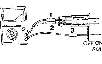
Fig. 17.27. Checking the driver's door limit switch
Checking the passenger door and rear side door limit switch
(The original article is on the website: mitsubishiman.ru)
- Use an ohmmeter to check the conductivity between the contacts of the passenger door limit switch connector and the rear side door at different positions of the switch plunger (Fig. 17.28). When the plunger is extended, there should be conductivity between contacts 1 and 2 of the connector, and when the plunger is pressed, there should be no conductivity.
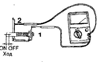
Fig. 17.28. Checking the passenger door and rear side door limit switch
Installation
- Installation is carried out in the reverse order of removal, taking into account the following.
- Lubricate the upper and lower door hinges with a universal grease (Fig. 17.29).
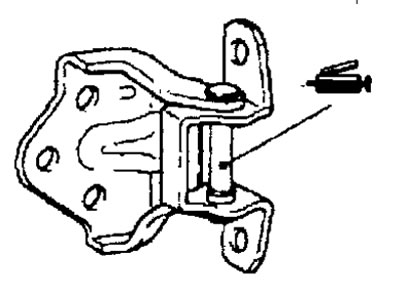
Fig. 17.29. Door hinge lubrication point
- Install the door and secure it with bolts to the hinges.
- Install the door opening limiter so that the marking is on top (Fig. 17.30) and secure it with bolts. Depending on the installation location, the limiter is marked with distinctive marks:
- FL - left front door;
- RL - left rear door;
- FR - right front door;
- RR - right rear door.
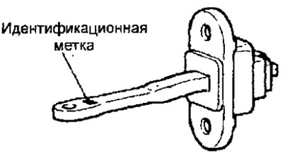
Fig. 17.30. Location of the identification mark on the door opening limiter
- Connect the electrical connector of the wire harness.
- If the closed door is not flush with the body surface, use a special tool to adjust its position after loosening the bolts securing the door hinges to the body.
- If the door is difficult to open and close, adjust the position of the lock and latch by adjusting the position of the latch (see fig. 17.22).