



2. Install the bearing shell with the oil channel on the cylinder block (Figure 4.35). Install the bearing shell without the oil channel on the main bearing cap. Install the upper axial clearance adjuster with the grooves toward the crankshaft wall.
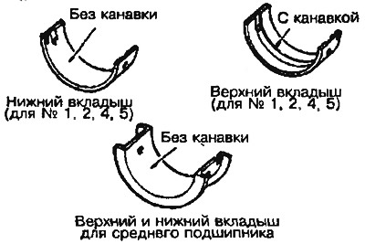
Figure 4.35. Inserts
Table 4.9. Identification of liners and cylinder block
| Crankshaft journal | Bearing hole in the cylinder block | Crankshaft liner | |
| Identification tag | Identification tag | Identification tag | Color label |
| 1 | 0 | S1 | Brown |
| 1 | S2 | Black | |
| 2 | S3 | Green | |
| 2 | 0 | S2 | Black |
| 1 | S3 | Green | |
| 2 | S4 | Yellow | |
| 3 | 0 | S3 | Green |
| 1 | S4 | Yellow | |
| 2 | S5 | Pink* | |
* old bearings may be marked in red