



The rear suspension is either a trailing arm or torsion beam suspension. Some models are equipped with an anti-roll bar.
The rack-and-pinion steering gear, located behind the power unit on the transverse bulkhead, controls the steering arms, which are combined with the steering knuckles. Most cars are equipped with power steering. The steering column is designed to collapse in the event of an accident.
Some models feature Electronically Controlled Suspension (ECS), which changes the shock absorber valve flow area to change the suspension stiffness depending on road conditions and driving style. The system includes a switch located on the center console, allowing the driver to select one of three modes: SPORT, AUTO or SOFT.
The ECS system receives information from various sensors located on the vehicle. The sensors send signals to the control module, which decides on the adjustment of the shock absorber. The shock absorber adjustment system is controlled by the electronic control unit (ECU) and the switch.
Due to the complexity of the system, troubleshooting and repair, other than finding loose connectors, faulty wires and blown fuses, should be left to your dealer.
Quite often, when working on suspension and steering systems, you will encounter fasteners that are difficult to separate. These fasteners are located under the vehicle and have been exposed to water, road dirt, etc. for a long time, so they are rusted or "frozen", which makes them very difficult to separate. To loosen such fasteners without damaging them (or other components), use a large amount of penetrating oil, allowing it to penetrate well. Use a wire brush to clean the outside of the threads, which will facilitate loosening and prevent thread damage. Sometimes a few sharp blows with a hammer or punch can be used to break the bond between the nut and bolt, but be careful not to let the tool slip and strip the threads. Heating the joint and surrounding area with a blowtorch can sometimes help, but this is not recommended due to the high risk of fire. You can increase the leverage with a pry bar or extension tube, but do not put an extension tube on the ratchet, as the ratchet may break. Sometimes you can try tightening the connection first (clockwise). Fasteners that require special measures to disconnect should be replaced.
Most of the work described in this chapter is performed from underneath the vehicle, so make sure you have a couple of strong supports. A hydraulic jack is a good choice for lifting the vehicle, and it is also useful for supporting various components during work.
Warning: Do not rely on a jack when working under the vehicle. After removing any suspension or steering fasteners, they must be carefully inspected and replaced with similar parts if necessary. To ensure proper assembly and secure fastening of components, it is important to follow the tightening torque specifications. Do not attempt to heat or straighten suspension or steering components. Replace bent or damaged components with new ones.
Original version of the article on the website: mitsubishiman
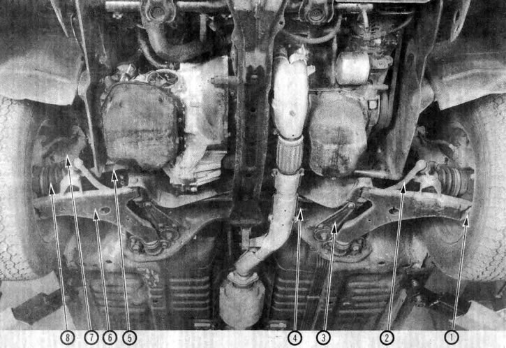
1.1a. View of front suspension and steering components from underneath the vehicle (Galant shown, Mirage, Tredla and Cordle similar). 1. Ball joint, 2. Anti-roll bar, 3. Support bracket, 4. Steering gear, 5. Drive shaft, 6. Lower control arm, 7. Strut and coil spring assembly, 8. Drive shaft boot
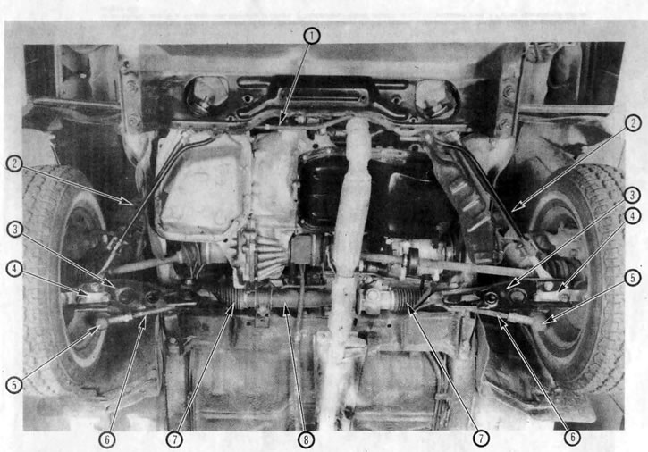
1.1b. View of front suspension and steering components from underneath the vehicle (Precis model shown). 1. Anti-roll bar, 2. Strut and coil spring assembly, 3. Lower control arm, 4. Ball joint, 5. Tie rod end, 6. Tie rod, 7. Steering gear boot, 8. Steering gear
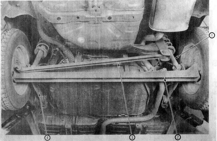
1.2a. View of rear suspension components from underneath the car (Galant model shown, Mirage, Tredla and Cordle models are similar). 1. Strut/shock absorber and coil spring assembly, 2. Rear axle torsion beam, 3. Transverse tie rod, 4. Rear axle torsion beam arm
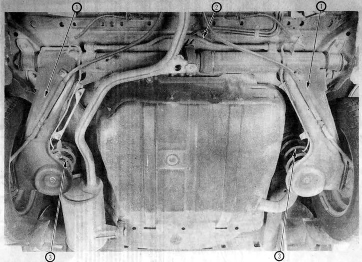
1.2b. View of rear suspension components from underneath the vehicle (Precis model shown). 1. Trailing arm, 2. Anti-roll bar, 3. Coil spring