



Contents: Generator for 2.0 and 2.6 L engines…⤓ Generator for 2.0 and 2.6 L engines…⤓ Diesel ⤓ Engines 2.4 l and 12-valve 3.0 l ⤓ Engines 3.0 l 24-valve and 3.5 l ⤓
Generator for 2.0 and 2.6 L engines (without air conditioning)
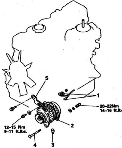
1. Connectors; 2. Generator; 3. Washers; 4. Axle bolt; 5. Plank
Removal
1. Turn off the ignition and disconnect the battery from ground.
2. Loosen the generator bolts and remove the drive belt. On some vehicles it will be necessary to remove the power steering pump.
3. Disconnect the generator wiring (having previously marked). Loosen the nuts of the terminal connections.
4. Unscrew the adjusting bolt and nut of the axle bolt, take measures to prevent the washers from falling out between the generator and the engine cover (installed on parts of cars).
5. Remove the axle bolt and remove the generator.
Installation
1. Install the generator in place. If a new unit is being installed, select new washers according to thickness. To do this, use a feeler gauge to check the gap between the front cover by pushing the generator forward. If the gap is more than 0.2 mm, then select washers so that they slide under slight force between the cover and the rear surface of the lower bracket.
2. Insert the axle bolt and tighten the nut.
3. Tighten the adjusting bolt and tighten the belt. Tighten the adjusting bolt to 12–13 N·m and the axle bolt to 20–24 N·m.
4. Install all removed parts.
Generator for 2.0 and 2.6 L engines (with air conditioning)
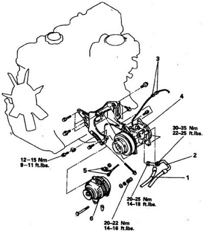
1. High pressure tube; 2. Low pressure tube; 3, 5. Connector; 4. Compressor; 6. Generator
Removal
1. Depressurize the air conditioner line by contacting a car service center.
2. Disconnect the tubes and connector from the compressor. Plug the holes immediately.
Loosen the axle and adjusting bolts, remove the drive belt and compressor, and move it to the side.
3. Loosen the generator bolts and remove the drive belt. Label and disconnect the connectors.
4. Unscrew the upper and then the lower bolt, taking precautions to prevent the adjusting washers from falling out. Remove the generator.
Installation
1. Install the generator in place, insert the lower bolt and select the lower bolt washers according to thickness so that the generator can be held and moved to the side with a little force. Tighten both bolts and tension the belt. Tighten the lower bolt to 13 N·m and the upper bolt to 28 N·m. Connect the wires.
2. Install the compressor in reverse order. First, tighten the belt slightly by feeding the compressor by hand without tightening the bolts, then tighten the bolts. Tighten the belt by turning the adjusting bolt. Immediately fill the line with refrigerant at a car service center.
3. If the belts have been changed, then after 80–160 km, check their tension again and adjust them.
Diesel
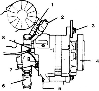
1, 6. Oil pipeline; 2. Vacuum hose; 3. Bolt of the bar; 4. Belt; 5. Axle bolt; 7. Terminal B; 8. Connector
Removal the generator cover
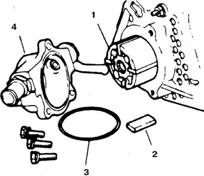
1. Rotor; 2. Shoulder blade; 3. Ring; 4. Body
Correct installation of pump blades
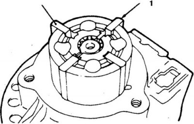
1. Rounding
Correct installation of the pump body
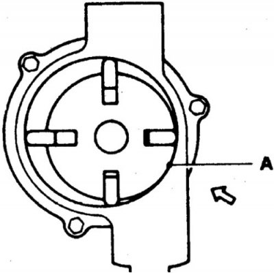
Move the pump in the direction of the arrow
Bolt tightening conditions
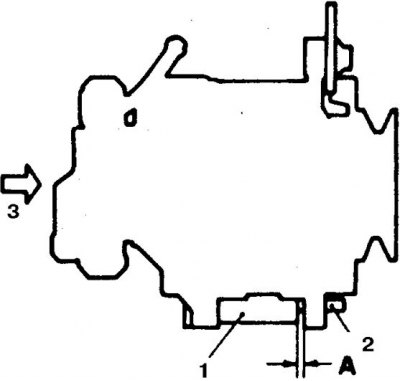
1. Front cover
2. Bolt
3. To measure the gap, move the generator in the direction of the arrow
The gap A must be compensated before tightening the bolt.
Removal
1. Turn off the ignition and disconnect the battery from ground.
2. Disconnect the wire from terminal B on the generator.
3. Disconnect the hoses from the vacuum pump.
4. Loosen the lock bolt, the lower bolt nut and remove the belt.
5. Loosen the through bolt and remove the generator assembly with the pump.
6. Loosen the bolts and carefully remove the pump.
7. Check the condition of the pump blades, ring and seal.
Installation
1. Installation is carried out in reverse order.
2. Installation of blades with the slightest defects is not permitted.
3. Install the pump body according to the photo (see figure Correct installation of the pump body).
4. First connect the hose to the pump, then install the generator.
5. Compensate for gap A (if it is more than 0.2 mm), having installed the washer.
6. Tighten the belt.
Engines 2.4 l and 12-valve 3.0 l
2.4L Engine Generator
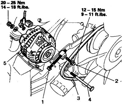
1. Adjusting bolt; 2. Lock bolt; 3. Belt; 4. Axle bolt; 5. Generator
Generator 12-valve engine 3.0 l
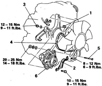
1. Adjusting bolt; 2. Lid; 3. Lock bolt; 4. Belt; 5. Axle bolt; 6. Generator
Removal
1. Turn off the ignition and disconnect the battery from ground.
2. Loosen the bolts and remove the belt. If you need to replace the belt, remove the power steering pump.
3. Disconnect the generator wiring (having previously marked). Loosen the nuts of the terminal connections.
4. Unscrew the lower bolt nut and the adjusting bolt. Remove the generator.
Installation
Installation is carried out in reverse order. Tighten the belt and tighten the bolts to the torque shown in the illustration.
Engines 3.0 l 24-valve and 3.5 l
Engine Generator 3.0L (24-valve) and 3.5 l
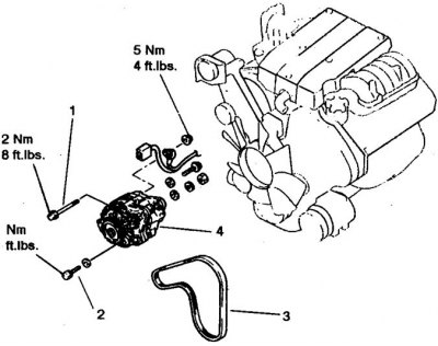
1. Axle bolt; 2. Lock bolt; 3. Belt; 4. Generator
Removal
1. Turn off the ignition and disconnect the battery from ground.
2. Raise the front of the vehicle.
3. Loosen the bolts and remove the belt. If you need to replace the belt, remove the power steering pump.
4. Disconnect the generator wiring (having previously marked). Loosen the nuts of the terminal connections.
5. Loosen the lock bolt and nut of the lower bolt. Remove the generator.
Installation
Installation is carried out in reverse order. Tighten the belt and tighten the bolts to the torque shown in the illustration.