



2. Using a dial indicator, measure the axial clearance of the primary shaft (Figure 11.255).
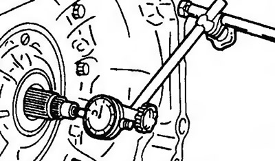
Figure 11.255. Using a dial indicator, measure the axial clearance of the primary shaft
3. Remove the automatic transmission oil level indicator. Unscrew the bolt, remove the gasket and the pressure pipe of the oil radiator.
4. Remove the oil filter (external mount model).
5. Remove the primary and secondary shaft speed sensors (Figure 11.256).
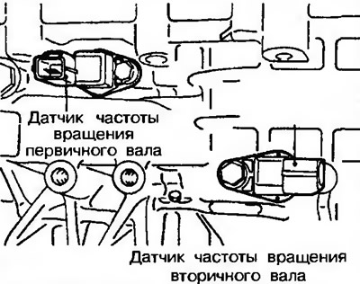
Figure 11.256. Remove the primary and secondary shaft speed sensors
6. Remove the gear shift lever and then remove the starter interlock switch (Figure 11.257).
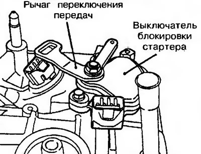
Figure 11.257. Remove the gear shift lever and then remove the starter interlock switch
7. Remove the speedometer drive gear or cap (Figure 11.258).
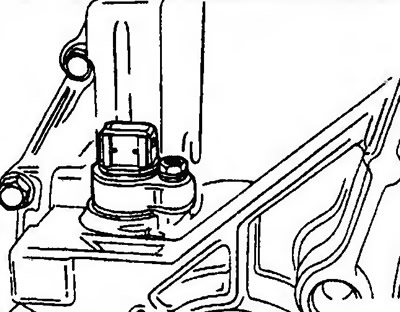
Figure 11.258. Remove the speedometer drive gear or cap
8. Remove the automatic transmission pan (valve block cover) (Figure 11.259).
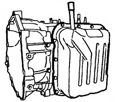
Figure 11.259. Remove the automatic transmission pan (valve block cover)
9. Remove the gearshift lever latch spring and then the latch itself (models before 1996) (Figure 11.260a).
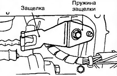
Figure 11.260a. Remove the gearshift lever latch spring and then the latch itself (models before 1996)
10. Remove the gear shift lever latch (models from 1997) (Figure 11.260b).
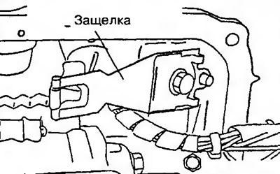
Figure 11.2606. Remove the gear shift lever latch (models from 1997)
11. Disconnect the wiring connector from the valve block (Figure 11.261).
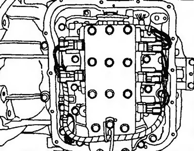
Figure 11.261. Disconnect the wiring connector from the valve block
12. Unscrew the 28 valve block mounting bolts (Figure 11.262). Remove the oil temperature sensor.
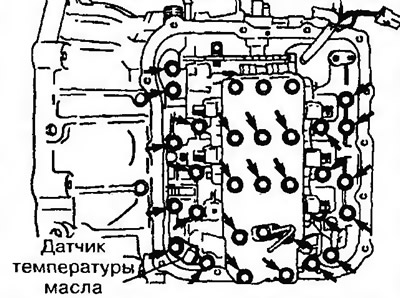
Figure 11.262. Unscrew the 28 valve block mounting bolts
13. Remove the valve block, gasket and two steel balls (Figure 11.263).
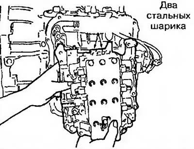
Figure 11.263. Remove the valve block, gasket and two steel balls
14. Remove the snap ring and then remove the solenoid valve wiring harness (Figure 11.264).
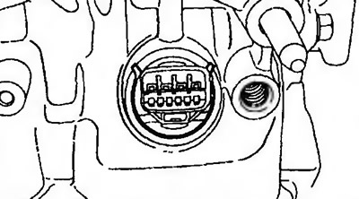
Figure 11.264. Remove the snap ring and then remove the solenoid valve wiring harness
15. Remove the mesh filter (left) and the 2nd gear shaft seal (right - see Figure 11.265).
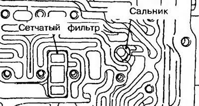
Figure 11.265. Remove the mesh filter and 2nd gear shaft seal
16. Remove the pistons and springs from the valve block (Figure 11.266).
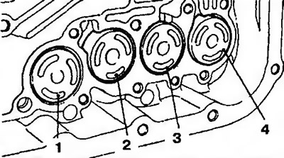
Figure 11.266. Remove the pistons and springs from the valve block
| № | Name |
| 1 | 1st gear and reverse gear lock |
| 2 | Downshift clutch |
| 3 | 2nd gear lock |
| 4 | Overdrive clutch |
17. Remove the gear shift lever roller.
18. Remove the gear shift lever and the automatic transmission parking lock rod (Figure 11.267).
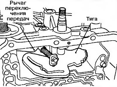
Figure 11.267. Remove the gear shift lever (on the right) and the automatic transmission parking lock rod
19. Unscrew the 18 bolts securing the torque converter housing, then remove the housing itself (Figure 11.268).
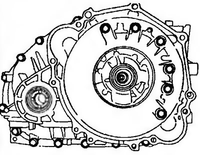
Figure 11.268. Unscrew the 18 bolts securing the GTR housing, then remove the housing itself
20. Remove the two sealing rings (Figure 11.269).
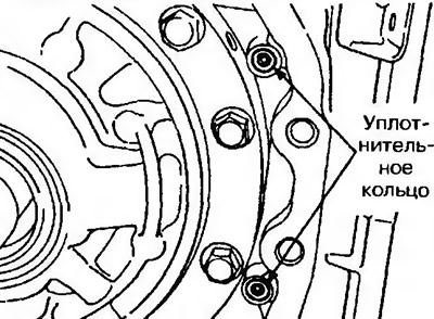
Figure 11.269. Remove the two sealing rings
21. Remove the differential and three inserts (automatic transmission F4A41-1-MRA) (Figure 11.270).
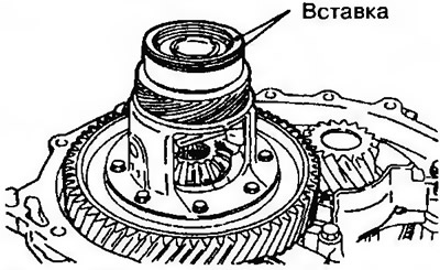
Figure 11.270. Remove the differential and three inserts
22. Remove the differential (automatic transmission F4A42, F4A51) (Figure 11.271).
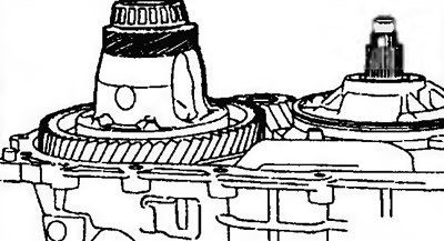
Figure 11.271. Remove the differential
23. Remove the oil filter (Figure 11.272).
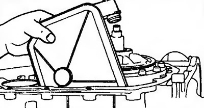
Figure 11.272. Remove the oil filter
24. Unscrew the six oil pump mounting bolts (Figure 11.273).
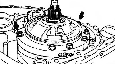
Figure 11.273. Unscrew the six oil pump mounting bolts
25. Insert special tool MD998333 into hole A and remove the oil pump (Figure 11.274).
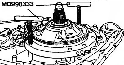
Figure 11.274. Insert special tool MD998333 into hole A and remove the oil pump
26. Remove the oil pump gasket.
27. Remove the washer (Figure 11.275).
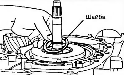
Figure 11.275. Remove the washer
28. Hold the primary shaft and remove the downshift clutch (Figure 11.276).
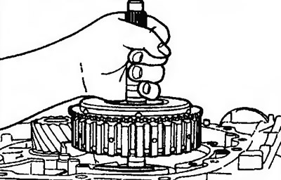
Figure 11.276. Holding the primary shaft, remove the downshift clutch
29. Remove the thrust bearing (Figure 11.277).
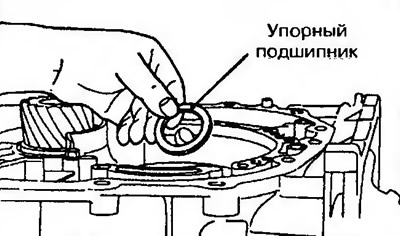
Figure 11.277. Remove the thrust bearing
30. Remove the downshift clutch hub (Figure 11.278).
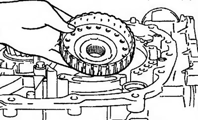
Figure 11.278. Remove the downshift clutch hub
31. Remove the rear cover, thrust rotating ring, four seals and the rear bearing of the input shaft (Figure 11.279).

Figure 11.279. Remove the rear cover, thrust rotating ring, four seals and the rear bearing of the primary shaft
32. Remove the three sealing rings (Figure 11.280).
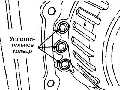
Figure 11.280. Remove the three sealing rings
33. Remove the reverse and overdrive clutch, as well as the thrust bearing (Figure 11.281).
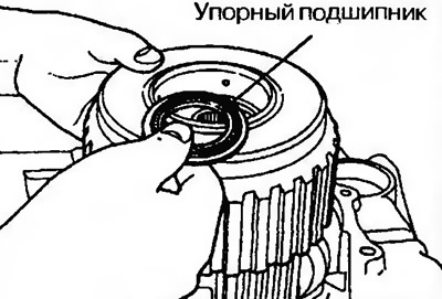
Figure 11.281. Remove the reverse and overdrive clutch and thrust bearing
34. Remove the overdrive clutch hub and thrust bearing (Figure 11.282).
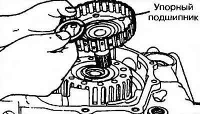
Figure 11.282. Remove the overdrive clutch hub and thrust bearing
35. Remove the thrust bearing (Figure 11.283).
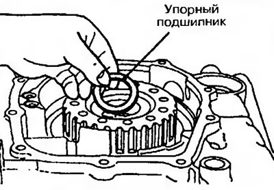
Figure 11.283. Remove the thrust bearing
36. Remove the reverse planetary gear sun gear (Figure 11.284).
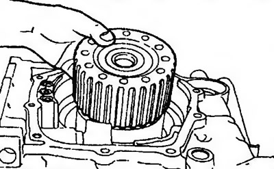
Figure 11.284. Remove the reverse planetary gear sun gear
37. Remove the spring retaining ring (Figure 11.285).
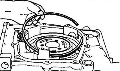
Figure 11.285. Remove the snap ring
38. Remove the 2nd gear lock piston and return spring (Figure 11.286).
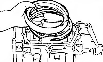
Figure 11.286. Remove the 2nd gear lock piston and return spring
39. Remove the pressure plate, brake discs and friction plates (Figure 11.287).
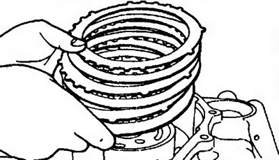
Figure 11.287. Remove the pressure plate, brake discs and friction plates
Number of brake discs and plates
| Model | Brake disc | Brake plate | Pressure plate |
| F4A41 | 2 | 1 | 1 |
| F4A42 | 3 | 2 | 1 |
| F4A51 | 4 | 3 | 1 |
40. Remove the planetary gear carrier of the overdrive gearbox (automatic transmission F4A41, F4A42-1 and F4A42-2 without a freewheel clutch) or the planetary gear carrier (automatic transmission F4A42-2 with a freewheel clutch and F4A51) (Figure 11.288).
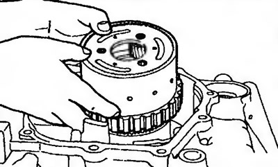
Figure 11.288. Remove the planetary gear carrier of the overdrive (automatic transmission F4A41, F4A42-1 and F4A42-2 without a freewheel clutch) or the planetary gear carrier (automatic transmission F4A42-2 with a freewheel clutch and F4A51)
41. Remove the secondary shaft planetary gear carrier and thrust bearing (automatic transmission F4A41, F4A42-1 and F4A42-2 without a freewheel clutch) (Figure 11.289).
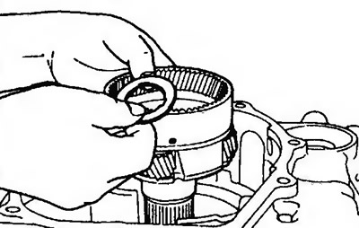
Figure 11.289. Remove the secondary shaft planetary gear carrier and thrust bearing (automatic transmission F4A41, F4A42-1 and F4A42-2 without a freewheel clutch)
42. Remove the downshift sun gear and thrust bearing (automatic transmission F4A41, F4A42-1 and F4A42-2 without a freewheel clutch) (Figure 11.290).
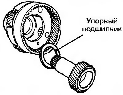
Figure 11.290. Remove the downshift sun gear and thrust bearing
43. Remove the spring retaining ring (Figure 11.291).
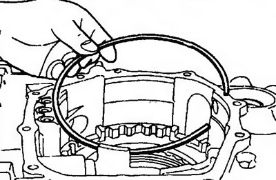
Fig. 11.291. Remove the snap ring
44. Remove the reaction and brake discs (Figure 11.292).
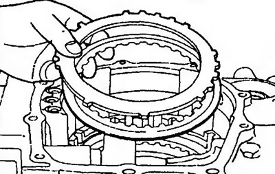
Figure 11.292. Remove the reaction and brake discs
45. Remove the snap ring (Figure 11.293).
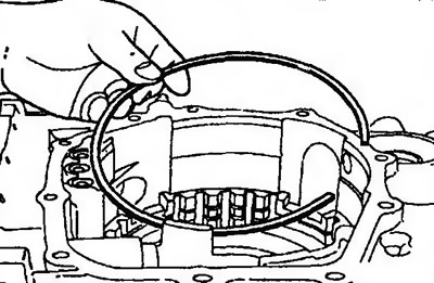
Figure 11.293. Remove the snap ring
46. Remove the friction plates, brake discs and pressure plate (Figure 11.294).
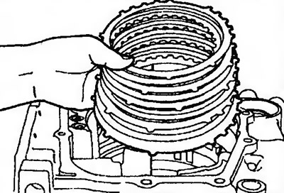
Figure 11.294. Remove the friction plates, brake discs and pressure plate
| Model | Brake disc | Brake plate | Pressure plate |
| F4A41 | 4 | 3 | 1 |
| F4A42-1 | 5 | 4 | 1 |
| F4A42-2, F4A51 | 6 | 5 | 1 |
47. Remove the shaft spring (Figure 11.295).
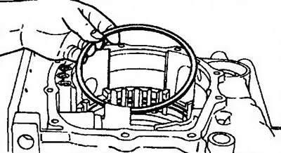
Figure 11.295. Remove the shaft spring
48. Remove the automatic transmission parking lock mechanism shaft, then remove the insert and spring (Figure 11.296).
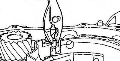
Figure 11.296. Remove the automatic transmission parking lock shaft, then remove the insert and spring
49. Remove the two rods of the automatic transmission parking lock drive, then remove the housing and support (Figure 11.297).
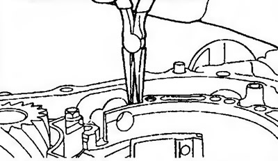
Figure 11.297. Remove the two rods of the automatic transmission parking lock drive, then remove the housing and support
50. Using a special tool, remove the snap ring.
51. Remove the inner rotating ring of the freewheel clutch (F4A42-2 with freewheel clutch and F4A51), sealing ring, spring retainer, return spring and 1st gear/reverse gear retainer piston (Figure 11.298).
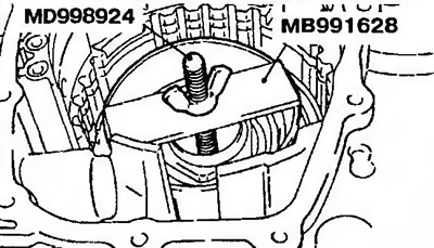
Figure 11.298. Remove the inner rotating ring of the freewheel clutch, the sealing ring, the spring retainer, the return spring and the piston of the 1st gear/reverse gear retainer
52. Unscrew the transfer case drive gear bearing mounting bolts (Figure 11.299).
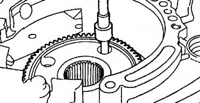
Figure 11.299. Unscrew the bolts securing the transfer case drive gear bearing
53. Remove the transfer case drive gear (Figure 11.300).
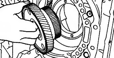
Figure 11.300. Remove the transfer case drive gear
54. Remove the cover (Figure 11.301).
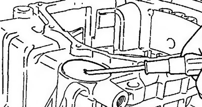
Figure 11.301. Remove the cover
55. Straighten the locking head of the secondary shaft lock nut (Figure 11.302).
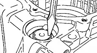
Figure 11.302. Straighten the secondary shaft lock nut locking head
56. Unscrew the secondary shaft lock nut (Figure 11.303).
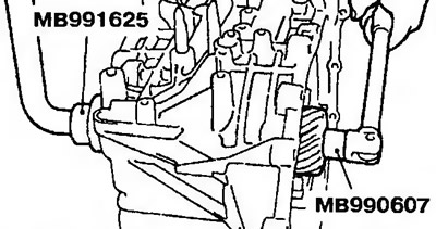
Figure 11.303. Unscrew the secondary shaft lock nut
57. Unscrew the bearing bracket mounting bolts (Figure 11.304).
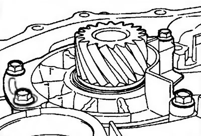
Figure 11.304. Unscrew the bearing bracket mounting bolts
58. Remove the secondary shaft, tapered roller bearings and sleeve (Figure 11.305).
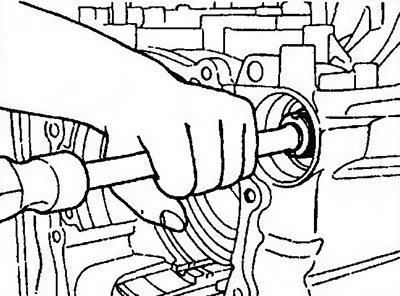
Figure 11.305. Remove the secondary shaft, tapered roller bearing and bushing
59. Remove the insert and outer rotating ring.
60. Remove the snap ring (Figure 11.306).
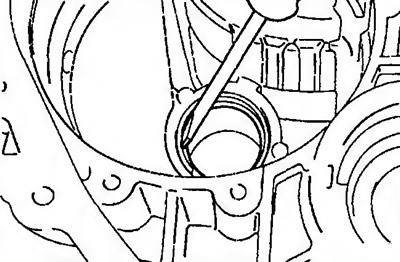
Figure 11.306. Remove the snap ring
61. Remove the outer rotating ring of the differential bearing and the insert from the torque converter housing (automatic transmission F4A42, F4A51).
62. Remove the outer rotating ring of the differential bearing from the gearbox housing (automatic transmission F4A42, F4A51).