



| Model | Special tool |
| F4A42 | MB990935, MB990938 |
| F4A51 | MB990936, MB990938 |
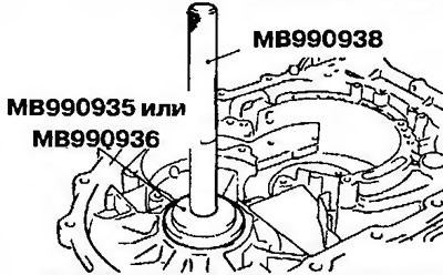
Figure 11.307. Press the outer rotating ring of the differential bearing into the gearbox housing (automatic transmission F4A42, F4A51)
64. Press the outer rotating ring of the secondary shaft bearing into the gearbox housing.
65. Install the old insert and snap ring.
66. Using special tools, install the transfer case gear (automatic transmission F4A41 since January 1998, F4A42-1 - since January 1998, F4A42-2 with freewheel clutch and F4A51) (Figure 11.308).
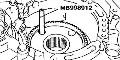
Figure 11.308. Using special tools, install the transfer case gear
67. Tighten the transfer case gear bearing mounting bolts to the required tightening torque (figure 11.299).
68. Install the 1st/reverse locking piston, return spring and spring lock (Figure 11.309). Check the identification grooves in the inner rotating ring of the freewheel clutch. Install the inner rotating ring of the freewheel clutch with the sealing ring in the transfer case pinion bearing so that the grooves are located along line A-A (F4A42-2 automatic transmission with freewheel clutch and F4A51).
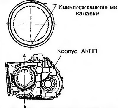
Figure 11.309. Install the 1st/reverse locking piston, return spring and spring lock. Check the identification grooves in the inner rotating ring of the freewheel clutch
69. Install the snap ring (figure 11.298).
70. Install the shaft spring (figure 11.295).
71. Install the brake discs, friction plates, indicator and snap ring (Figure 11.310 a, b).
Attention! At this point, the pressure plate cannot be installed yet.
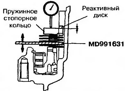
Figure 11.310a. Install the brake discs, friction plates, indicator and snap ring and check the axial clearance (automatic transmission F4A41, F4A42-1 up to December 1997, F4A42-2 without freewheel clutch) | 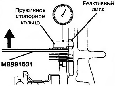
Figure 11.3106. Install the brake discs, friction plates, indicator and snap ring and check the axial clearance (automatic transmission F4A41, F4A42-1 from January 1998) |
72. Install the reaction disk and used snap ring.
73. Using a dial indicator, measure the axial clearance. Based on the measurements, select a snap ring that will provide the required clearance. Replace the snap ring used in step 70 with the selected ring. Nominal clearance: 0-0.16 mm.
74. Install the brake discs, friction plates and indicator МВ991631 (automatic transmission F4A41, F4A42) or МВ991632 (automatic transmission F4A51) (Figure 11.311a-g).
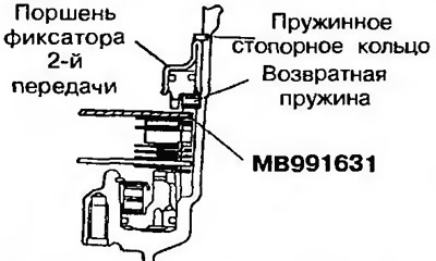
Figure 11.311 a. Install the brake discs, friction plates and indicator MB991631 (automatic transmission F4A41 and F4A42-1 before December 1997) | 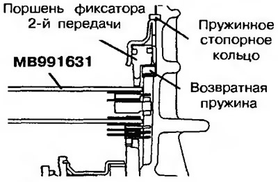
Figure 11.311b. Install the brake discs, friction plates and indicator МВ991631 (automatic transmission F4A41 since January 1998) |
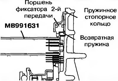
Figure 11.311v. Install the brake discs, friction plates and indicator МВ991631 (АКППР4А42-1 since January 1998) | 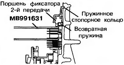
Figure 11.311g. Install the brake discs, friction plates and indicator МВ991631 (АКППР4А42-1 with a freewheel clutch since January 1998) |
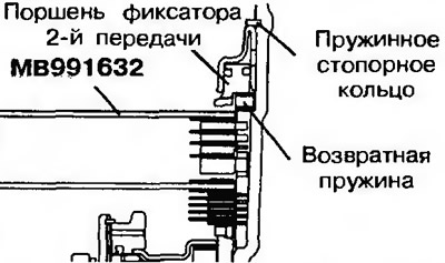
Figure 11.311d. Install the brake discs, friction plates and indicator МВ991632 (automatic transmission F4A51)
Number of brake discs and plates
| Model | Brake disc | Brake plate |
| F4A41 | 2 | 1 |
| F4A42 | 3 | 2 |
| F4A51 | 4 | 3 |
75. Install the return spring, 2nd gear lock piston and snap ring.
76. Measure the axial clearance and select from tables 11.3a or 11.3b a pressure plate whose thickness will correspond to the measured axial clearance (Figure 11.312).
Nominal axial clearance: automatic transmission F4A41 - 0.49-0.95 mm, automatic transmission F4A42 - 0.79-1.25 mm, automatic transmission F4A51 - 1.09-1.55 mm.
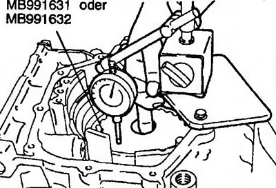
Figure 11.312. Measure the axial clearance and select a pressure plate whose thickness will correspond to the measured axial clearance
Table 11.3. Pressure plate for F4A41 and F4A42
| Displacement value, mm | Thickness, | Identification tag | Part No | |
| F4A41 | F4A42 | |||
| 0.3-0.5 | 0.6-0.8 | 1.6 | L | MD759567 |
| 0.5-0.7 | 0.8-1.0 | 1.8 | 1 | MD759414 |
| 0.7-0.9 | 1.0-1.2 | 2.0 | 0 | MD759415 |
| 0.9-1.1 | 1.2-1.4 | 2.2 | 2 | MD759416 |
| 1.1-1.3 | 1.4-1.6 | 2.4 | 4 | MD759417 |
| 1.3-1.5 | 1.6-1.8 | 2.6 | 6 | MD759418 |
Table 11.3b. Pressure plate for F4A51
| Displacement value, mm | Thickness, mm | Identification tag | Part No |
| 1.1-1.3 | 1.8 | E | MD759425 |
| 1.3-1.5 | 2.0 | D | MD759426 |
| 1.5-1.7 | 2.2 | WITH | MD759427 |
| 1.7-1.9 | 2.4 | IN | MD759428 |
| 1.9-2.1 | 2.6 | A | MD759429 |
| 2.1-2.3 | 2.8 | 0 | MD759430 |
77. Turn the gearbox over.
78. Insert the MD998913 rod into the dial indicator and measure the axial clearance using the MB991631 or MB991632 indicator (Figure 11.313). Select from Tables 11.4a or 11.4b a pressure plate whose thickness will correspond to the measured axial clearance.
Nominal axial clearance: automatic transmission F4A41 - 1.05-1.51 mm, automatic transmission F4A42-1 - 1.35-1.81 mm, automatic transmission F4A42-2 and F4A51 - 1.65-2.11 mm.
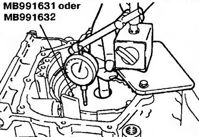
Figure 11.313. Insert the MD99B913 rod into the dial indicator and measure the axial clearance using the MB991631 or MB991632 indicator
Table 11.4a. Pressure plate for F4A41 and F4A42
| Displacement value, mm | Thickness, mm | Identification tag | Part No | ||
| F4A41 | F4A42-1 | F4A42-1 | |||
| 0.7-0.9 | 1.0-1.2 | 1.3-1.5 | 1.6 | L | MD759567 |
| 0.9-1.1 | 1.2-1.4 | 1.5-1.7 | 1.8 | 1 | MD759414 |
| 1.1-1.3 | 1.4-1.6 | 1.7-1.9 | 2.0 | 0 | MD759415 |
| 1.3-1.5 | 1.6-1.8 | 1.9-2.1 | 2.2 | 2 | MD759416 |
| 1.5-1.7 | 1.8-2.0 | 2.1-2.3 | 2.4 | 4 | MD759417 |
| 1.7-1.9 | 2.0-2.2 | 2.3-2.5 | 2.6 | 6 | MD759418 |
| 1.9-2.1 | 2.2-2.4 | 2.5-2.7 | 2.8 | 8 | MD759419 |
| 2.1-2.3 | 2.4-2.6 | 2.7-2.9 | 3.0 | D | MD759420 |
Table 11.4b. Pressure plate for F4A51
| Displacement value, mm | Thickness, mm | Identification symbol | Part No |
| 1.0-1.2 | 1.6 | F | MD759568 |
| 1.2-1.4 | 1.8 | E | MD759425 |
| 1.4-1.6 | 2.0 | D | MD759426 |
| 1.6-1.8 | 2.2 | WITH | MD759427 |
| 1.8-2.0 | 2.4 | IN | MD759428 |
| 2.0-2.2 | 2.6 | A | MD759429 |
| 2.2-2.4 | 2.8 | 0 | MD759430 |
| 2.4-2.6 | 3.0 | 1 | MD759431 |
79. Remove all installed measuring and additional devices.
80. Install the secondary shaft into the gearbox housing and tighten the secondary shaft bearing bracket mounting bolt to the required torque (Figure 11.304).
81. Install the sleeve and tapered roller bearing on the secondary shaft (Figure 11.314).
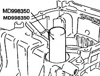
Figure 11.314. Install the sleeve and tapered roller bearing on the secondary shaft
82. Lubricate the new lock nut with transmission fluid and tighten it to the specified torque. Then loosen it one turn and tighten it again.
83. Move the secondary shaft to measure the axial clearance and select the insert within the following limits (Figure 11.315): from (Axial clearance + Thickness of old insert + 0.01 mm) to (Axial clearance + Thickness of old insert + 0.09 mm).
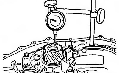
Figure 11.315. Move the secondary shaft to measure the axial clearance and select the insert
84. Lock the lock nut with a center punch (in two places) (Figure 11.316).
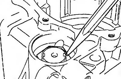
Figure 11.316. Lock the lock nut with a center punch (in two places)
85. Install the cover (Figure 11.317).
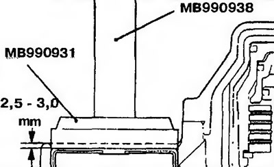
Figure 11.317. Install the cover
86. Install the transfer case drive gear (Figure 11.308).
87. Tighten the four transfer case drive pinion mounting bolts (figure 11.299).
88. Install the automatic transmission parking lock mechanism, insert and spring. Then install the automatic transmission parking lock mechanism rod (Figure 11.318).
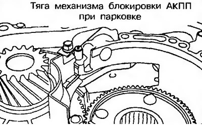
Figure 11.318. Install the automatic transmission parking lock mechanism, insert and spring. Then install the automatic transmission parking lock mechanism rod
89. Install the support of the automatic transmission parking lock mechanism and two (Figure 11.319).
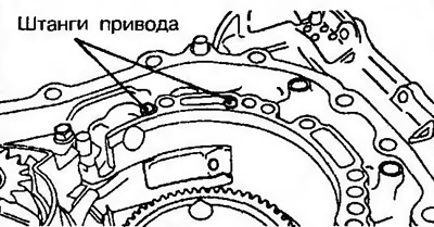
Figure 11.319. Install the automatic transmission parking lock support and two drive rods
90. Install the reduction gear sun gear and thrust bearing on the secondary shaft planetary gear carrier (F4A41, F4A42-1 and F4A42-2 without overrunning clutch) (Figure 11.320).
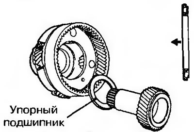
Figure 11.320. Install the downshift sun gear and thrust bearing on the secondary shaft planetary gear carrier
91. Install the secondary shaft planetary gear carrier and thrust bearing (F4A41, F4A42-1 and F4A42-2 without overrunning clutch) (Figure 11.321).
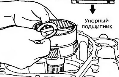
Figure 11.321. Install the secondary shaft planetary gear carrier and thrust bearing
92. Install the overdrive planetary gear carrier (F4A41, F4A42-1 and F4A42-2 without overrunning clutch) or the planetary gear carrier (F4A42-2 with overrunning clutch and F4A51) (figure 11.288).
93. Install the reverse planetary gear sun gear (figure 11.284).
94. Install the shaft spring (figure 11.295).
95. Install the pressure plate, brake discs and friction plates (Figure 11.322).
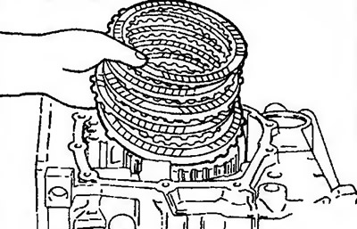
Figure 11.322. Install the pressure plate, brake discs and friction plates
Number of brake discs and friction plates
| Model | Brake discs | Friction plates | Pressure plate |
| F4A41 | 4 | 3 | 1 |
| F4A42-1 | 5 | 4 | 1 |
| F4A42-2, F4A51 | 6 | 5 | 1 |
96. Install the spring retaining ring (Figure 11.323).
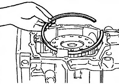
Figure 11.323. Install the snap ring
97. Install the reaction disk (Figure 11.324).
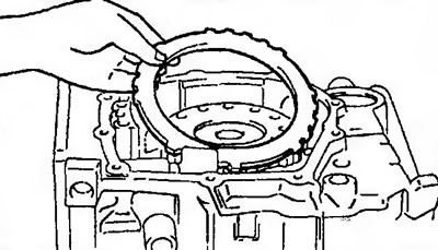
Figure 11.324. Install the reaction disk
98. Install the spring retaining ring (Figure 11.325).
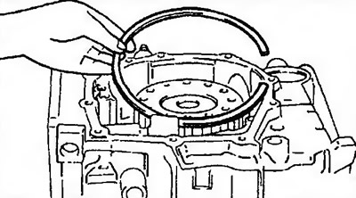
Figure 11.325. Install the snap ring
99. Install the brake discs, friction plates and pressure plate (Figure 11.326).
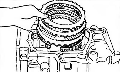
Figure 11.326. Install the brake discs, friction plates and pressure plate
100. Install the return spring and 2nd gear lock piston (figure 11.286).
101. Install the snap ring (Figure 11.327).
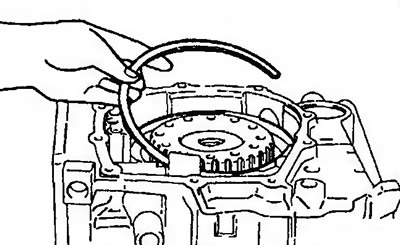
Figure 11.327. Install the snap ring
102. Install the thrust bearing (Figure 11.328).
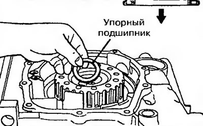
Figure 11.328. Install the thrust bearing
103. Install the overdrive clutch hub and thrust bearing into the reverse/overdrive clutch (Figure 11.329).
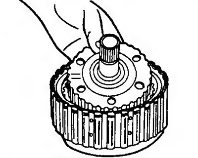
Figure 11.329. Install the overdrive clutch hub and thrust bearing into the reverse/overdrive clutch
104. Install the reverse/overdrive clutch and thrust bearing (Figure 11 330).
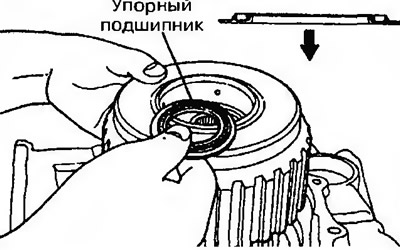
Figure 11.330. Install the reverse/overdrive clutch and thrust bearing
105. Install the three sealing rings (figure 11.280).
106. Press the primary shaft bearing into the rear cover (Figure 11.331).
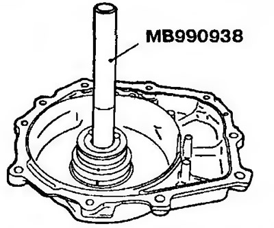
Figure 11.331. Press the primary shaft bearing into the rear cover
107. Install four oil seals into the groove of the rear cover.
108. Install the thinnest rotating ring (1.6 mm thick) on the thrust bearing, install the rear cover and tighten the bolts to the required torque. Measure the axial clearance of the downshift sun gear (Figure 11.332). Nominal clearance: 0.25-0.45 mm. Select a rotating ring from Table 11.5 whose thickness corresponds to the measured clearance and replace the previously installed ring with the selected ring.
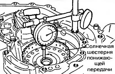
Figure 11.332. Install the thinnest rotating ring (1.6 mm thick) on the thrust bearing, install the rear cover and tighten the bolts to the required torque. Measure the axial clearance of the downshift sun gear
Table 11.5. Rotating ring thickness
| Measured parameter, mm | Thickness, mm | Part No |
| 0.3-0.4 | 1.6 | MD707267 |
| 0.4-0.5 | 1.7 | MD759681 |
| 0.5-0.6 | 1.8 | MD723064 |
| 0.6-0.7 | 1.9 | MD754794 |
| 0.7-0.8 | 2.0 | MD707268 |
| 0.8-0.9 | 2.1 | MD754795 |
| 0.9-1.0 | 2.2 | MD723065 |
| 1.0-1.1 | 2.3 | MD754796 |
| 1.1-1.2 | 2.4 | MD724358 |
| 1.2-1.3 | 2.5 | MD754797 |
| 1.3-1.4 | 2.6 | MD754798 |
109. Install the back cover (Figure 11.279).
110. Install the downshift clutch hub (Figure 11.278).
111. Install the thrust bearing (Figure 11.333).
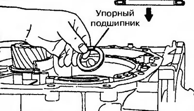
Figure 11.333. Install the thrust bearing
112. Holding the input shaft, install the downshift clutch (figure 11.276).
113. Install two pieces of soldering wire (each 10 mm long and 3.5 mm in diameter) onto the downshift clutch pin (Figure 11.334).
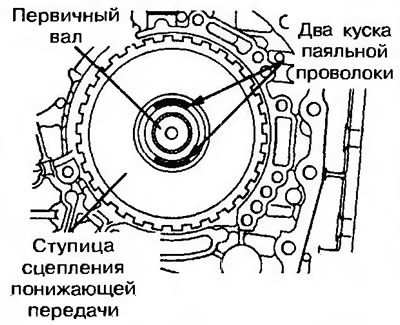
Figure 11.334. Install two pieces of soldering wire (each 10 mm long and 3.5 mm in diameter) onto the downshift clutch hub
114. Install the special tool and install the oil pump into the gearbox housing (Figure 11.335).
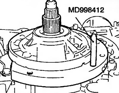
Figure 11.335. Install the special tool and install the oil pump into the gearbox housing
115. Tighten and loosen the oil pump mounting bolts (6 pieces).
116. Using a special tool, remove the oil pump (figure 11.274). After this, remove the compressed pieces of soldering wire. Measure the thickness of the compressed wire with a micrometer. Select from Table 11.6 a thrust disc whose thickness corresponds to the measured gap.
Table 11.6. Thrust disc thickness
| Measured value, mm | Thickness, mm | Identification tag | Part No |
| 2.25-2.45 | 1.8 | 18 | MD754509 |
| 2.45-2.65 | 2.0 | 20 | MD754508 |
| 2.65-2.85 | 2.2 | 22 | MD754507 |
| 2.85-3.05 | 2.4 | 24 | MD753793 |
| 3.05-3.25 | 2.6 | 26 | MD753794 |
| 3.25-3.45 | 2.8 | 28 | MD753795 |
117. Install the thrust disc selected in this way into the downshift clutch bracket (figure 11.275).
118. Install the new oil pump gasket and oil pump.
119. Tighten the oil pump mounting bolts.
120. Check the axial clearance of the primary shaft, which should correspond to the required one (Figure 11.336). Required clearance: 0.70-1.45 mm.
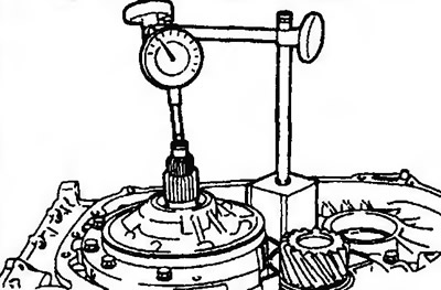
Figure 11.336. Check the axial clearance of the primary shaft
121. Install the oil filter (figure 11.272).
122. Install the insert (only for automatic transmission F4A41-1-MRA) and then the differential (automatic transmission F4A41) (figure 11.270).
123. Install the differential (automatic transmission F4A42, F4A51) (Figure 11.271).
124. Install a 1.25 mm thick insert (only for F4A41-1-MRA automatic transmission).
125. Install a 10 mm long and 3 mm diameter soldering wire onto the differential (automatic transmission F4A41) (Figure 11.337).
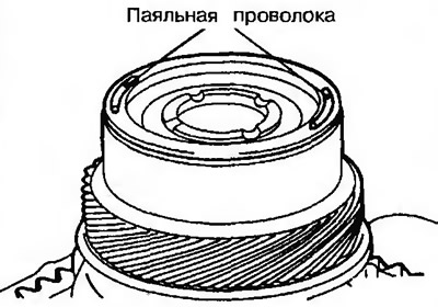
Figure 11.337. Install a 10 mm long and 3 mm diameter soldering wire on the differential (automatic transmission F4A41)
125. Place the soldering wire 10 mm long and 3 mm in diameter and the outer rotating ring on the transformer body as shown in Figure TFA1527 (F4A42, F4A51).
126. Install the torque converter housing without sealant into the automatic transmission housing and tighten its mounting bolts to the required tightening torque.
127. Unscrew the bolts, remove the outer rotating ring (automatic transmission F4A42, F4A51) and soldering wire.
128. Use an indicator to measure the thickness of the compressed soldering wire (figure 11.15). Select an insert whose thickness must be within the range defined by the following formula:
- Automatic transmission F4A41: from (T -0.045 mm) to (T -0.165 mm).
- Automatic transmission F4A42, F4A51: from (T +0.045 mm) to (T +0.105 mm).
130. Install the selected insert (automatic transmission F4A41) (figure 11.270).
131. Install the mesh filter and the 2nd gear lock bracket seal (figure 11.265).
132. Install the solenoid valve wiring connector and snap ring (figure 11.264).
133. Install the valve block, gasket and two steel balls (figure 11.263).
134. Install the oil temperature sensor (figure 11.262).
135. Tighten the 28 valve block mounting bolts.
136. Connect the wiring connectors to the valve block (figure 11.261).
137. Install the gear shift lever spring and latch (figure 11.260a,b).
138. Install the valve block cover and tighten its mounting bolts (figure 11.259).
139. Install the speedometer gear or cap (figure 11.258).
140. Install the starter interlock switch and gear shift lever (figure 11.257).
141. Install the primary and secondary shaft speed sensors (figure 11.256).
142. Install the oil level indicator.
143. Further assembly is carried out in the reverse order of removal.
| № | Knot | Wire color | Color of the wiring connector |
| 1 | Downshift Solenoid Valve | White, red, red | Black |
| 2 | Overdrive solenoid valve | Orange, red | Black |
| 3 | 1st/Reverse Solenoid Valve | Brown, yellow | Milky white |
| 4 | 2nd gear brake solenoid valve | Green, red, red | Milky white |
| 5 | Damper clutch control solenoid valve | Blue, yellow, yellow | Black |
| 6 | Oil temperature sensor | Black, red | Black |