



Contents: Checking the operating voltage of…⤓ Checking the battery terminals, fuse…⤓ Checking the drive belt ⤓ Checking the Alternator Wiring ⤓ Checking the AC generator by ear ⤓ Checking the charging light ⤓ Measuring the electrical voltage in…⤓ Checking the voltage regulator ⤓
Checking the operating voltage of the battery
1. Start the engine and let it run for about twenty minutes, then turn off the engine.
2. Turn the ignition key to the "ON" position and turn on all electrical systems (lighting, air conditioning) for one minute to relieve excess tension.
3. Turn the ignition key to the "OFF" position and turn off all electrical systems (lighting, air conditioning). Then connect the voltmeter to the battery and measure the voltage between the battery terminals.
Standard voltage value: 12.5-12.9V at 20°C.
Note: If the voltage is less than the specification voltage, replace the battery.
Checking the battery terminals, fuse box and fusible links
1. Check for damage or corrosion on the battery terminals.
2. Check the fuse box and fusible links for continuity.
Checking the drive belt
1. Check the belt for intensive wear, cord wear, etc.
Note: If any of these defects are found, the belt must be replaced. Cracks on the ribbed surface of the belt are not allowed. If there are areas on the belt where there are no ribs, the belt must be replaced.
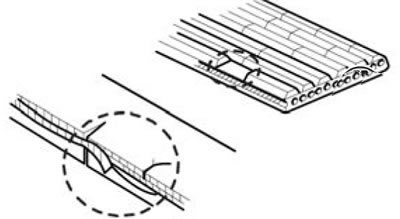
2. Check that the drive belt is installed correctly.
Note: Check manually that the belt is in the grooves of the drive pulley and has not slipped to the side.
Note:
- Check the belt deflection at the special points indicated in the figure.
- When installing a new belt, set the belt tension to specification.
- After the new belt has been running for more than 5 minutes, check and ensure that the belt deflection is within the specification of the new belt.
- After installing and running the old belt for more than 5 minutes, check and make sure the belt deflection matches the specification value of the old belt.
- Check the tension and deflection of the V-belt after the crankshaft has made two full revolutions.
Checking the Alternator Wiring
Visually check the condition of the alternator wiring.
Checking the AC generator by ear
Check the alternator for abnormal sounds when the engine is running.
Checking the charging light
1. Turn the ignition key to the "ON" position.
2. Check if the charging light comes on.
3. Start the engine.
4. Check if the charging light has gone out.
Note: If the charging light does not go out, check the charging system.
Measuring the electrical voltage in the output circuit of an alternator
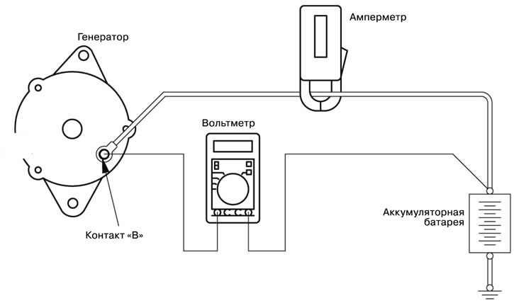
The purpose of this test is to determine the condition of the cable wiring (including fuse wire) between terminal B of the alternator and the positive terminal (+) of the battery.
1. Before testing, the following must be checked:
- 1) Mounting position and reliable current.
- 2) Tension of the alternator drive belt.
- 3) Condition of the fuse wire.
- 4) The presence of abnormal noise from the alternator when the engine is running.
2. Set the ignition key to the "OFF" position.
3. Disconnect the cable from the negative battery terminal.
4. Disconnect the output cable from terminal B of the alternator, connect in series a DC ammeter with a scale of 1-100A intended for testing to terminal B of the alternator and the disconnected output cable (the positive terminal (+) of the ammeter is connected to terminal B, and the negative terminal (-) of the ammeter is connected to the removed output cable of the alternator).
Note: It is preferable to use a clamp-on ammeter, which can be connected as described above even without disconnecting the alternator output cable. A poor closure of contact B will result in a decrease in the induced electrical voltage.
5. Connect a digital voltmeter between terminal B of the alternator and the positive terminal (+) of the battery (the positive terminal of the voltmeter (+) is connected to terminal B of the alternator, the negative terminal (-) is connected to the positive terminal (-) of the battery).
6. Reconnect the cable to the negative terminal of the battery.
7. Install a tachometer to measure engine speed.
8. Open the engine hood and secure it in the open position.
9. Start the engine.
10. At an engine speed of 2500 rpm, change the engine load by turning on and off the headlights and other lighting devices. The ammeter needle should show a current value slightly higher than 30A. Gradually adjust the engine speed so that the ammeter needle is set exactly at 30A, read the voltmeter readings in this mode.
Maximum permissible operating value: no more than 0.3V.
Note: If the alternator output is too high and the ammeter needle cannot be set to exactly 30A, you can adjust the engine speed to the appropriate current of 40A and read the voltmeter in this mode. In this case, the maximum permissible operating value should not exceed 0.4V.
11. If the voltmeter shows a voltage that exceeds the maximum permissible value, it can be assumed that there is a fault in the output circuit of the alternator. In this case, it is necessary to check the cable bus between the generator terminal B and the positive terminal (+) of the battery.
12. After completing the tests, let the engine run for some time in idle mode.
13. Turn off all headlights and lighting devices, then turn off the ignition.
14. Turn off the tachometer.
15. Disconnect the cable from the negative battery terminal.
16. Disconnect the ammeter and voltmeter.
17. Connect the output cable to terminal B of the alternator.
18. Connect the cable to the negative terminal of the battery.
Checking the voltage regulator
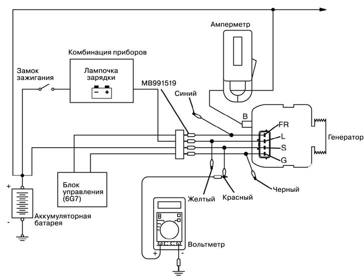
This test determines if the generator voltage regulator is properly controlling the generator output voltage.
1. Before you start testing, always check the following:
- Installation of a generator.
- The battery must be fully charged.
- Generator drive belt tension.
- Fuse link.
- No extraneous noise when the generator is running.
2. Turn the ignition key to the OFF position.
3. Disconnect the wire from the (-) terminal of the battery.
The text of the article was obtained from the website: MitsubishiMan
4. Use a special tool to connect the digital voltmeter (generator Test Wire Harness MB991519, MB991450). Connect the (+) lead of the voltmeter to the "S" terminal of the generator, and then securely connect the (-) lead of the voltmeter to ground or connect it to the (-) terminal of the battery.
5. Disconnect the wire from the "B" terminal of the generator.
6. Connect the (+) wire of a 0-100 A DC ammeter to the "B" terminal of the generator, and the (-) wire of the ammeter to the disconnected standard wire.
7. Connect the wire from the (-) terminal of the battery.
8. Connect the tachometer or MUT-II.
9. Turn the ignition key to the ON position and check that the voltmeter reading is equal to the battery voltage.
Note: If the voltmeter shows "0" V, then there is probably a break in the circuit between the "S" terminal of the generator and the (+) terminal of the battery (including in the fuse link).
10. Turn off all lights and additional electrical equipment in the vehicle.
11. Start the engine.
12. Set the engine speed to 2500 rpm.
13. Read the voltmeter readings when the generator output current is 10 A or less.
14. If the voltmeter readings correspond to the nominal values of the regulated voltage, then the voltage regulator is working properly. If the voltmeter readings do not correspond to the range of nominal values, then either the voltage regulator or the generator is faulty.
15. After completing the check, let the engine idle.
16. Turn off the ignition.
17. Disconnect the tachometer or MUT-III.
18. Disconnect the wire from the (-) terminal of the battery.
19. Disconnect the ammeter and voltmeter.
20. Connect the standard wire to the "B" terminal of the generator.
21. Remove the special tool and connect the generator electrical connector.
22. Connect the wire to the (-) terminal of the battery.
Table of nominal values of regulated voltage:
| Verifiable output | Air temperature near the voltage regulator (in the engine compartment),°C | Voltage, V |
| Output "S" | -20 | 14,2-15,4 |
| 20 | 13,9- 14,9 | |
| 60 | 13,4- 14,6 | |
| 80 | 13,1 -14,5 |