



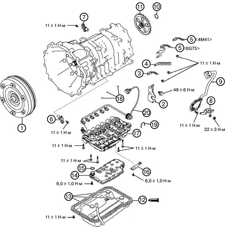
Note: Mark the wires and tubes to avoid incorrect installation.
1. Remove the torque converter (1).
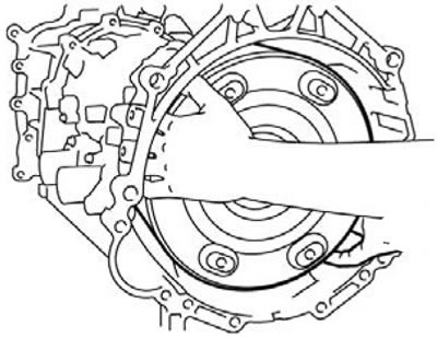
2. Remove the cable end bracket (2).
3. Remove the clamp (3).
4. Remove the clamp (4).
5. Remove the wiring bracket (5).
6. Remove the input shaft speed sensor (6).
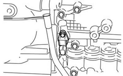
7. Remove the output shaft speed sensor (7).
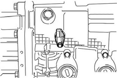
8. Remove the manual control lever (8).
9. Remove the park/neutral switch (9).
10. Remove the spring ring (10).
11. Remove the parking gear (11).
1) Remove the spring ring and remove the parking gear using a puller (clamping force approx. 9.8 N).
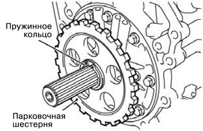
12. Remove the oil pan (12).
1) Unscrew the twenty oil pan mounting bolts and then remove the oil pan using a special tool.
Caution: Be careful not to apply impact loads to avoid damaging the mounting surface of the oil pan when removing.
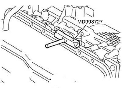
13. Remove the magnet (13).
14. Remove the oil filter (14).
15. Remove the sealing ring (15).
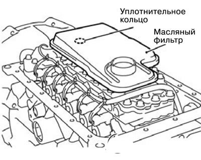
16. Remove the locking spring (16).
17. Remove the valve body (17).
1) Remove the twenty mounting bolts and then remove the valve body, three sealing rings and the oil temperature sensor.
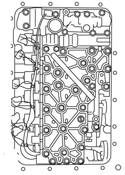
18. Remove the sealing ring (18).
19. Remove the spring ring (19).
20. Remove the solenoid valve wiring (20).
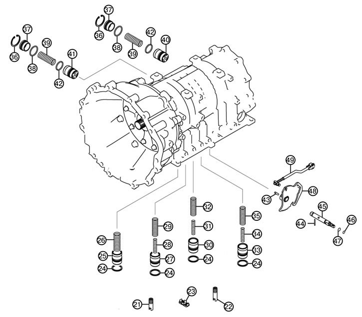
21. Remove the oil seal (21).
22. Remove the oil seal (22).
23. Remove the oil filter (23).
24. Remove the sealing ring (24).
25. Remove the hydraulic accumulator piston (25).
26. Remove the hydraulic accumulator spring (26).
27. Remove the hydraulic accumulator piston (27).
28. Remove the inner spring (28).
29. Remove the outer spring (29).
30. Remove the hydraulic accumulator piston (30).
31. Remove the inner spring (31).
32. Remove the outer spring (32).
33. Remove the hydraulic accumulator piston (33).
34. Remove the inner spring (34).
35. Remove the outer spring (35).
H6. Remove the spring ring (36).
37. Remove the accumulator cover (37).
38. Remove the sealing ring (38).
39. Remove the hydraulic accumulator spring (39).
40. Remove the hydraulic accumulator piston (40).
41. Remove the hydraulic accumulator piston (41).
42. Remove the sealing ring (42).
43. Remove the spring pin (43).
44. Remove the pin (44).
45. Remove the manual control shaft (45).
46. Remove the sealing ring (46).
47. Remove the sealing ring (47).
48. Remove the locking lever (48).
49. Remove the parking roller rod (49).
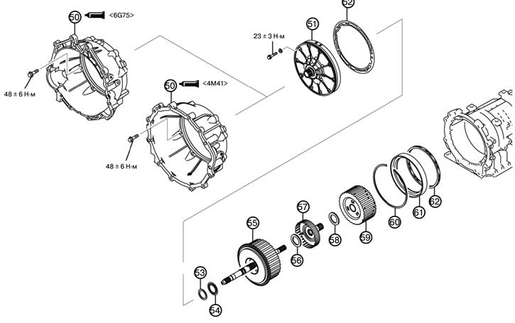
50. Remove the torque converter housing (50).
1) Unscrew the eight mounting bolts and remove the torque converter housing.
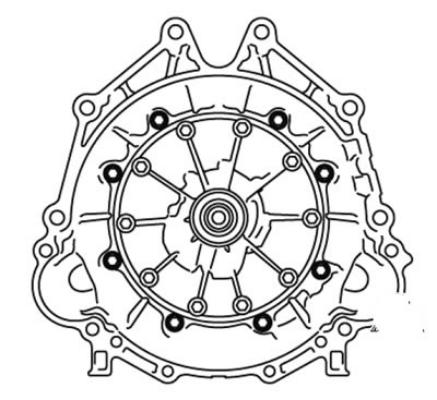
51. Remove the oil pump (51).
1) Remove the ten oil pump mounting bolts.
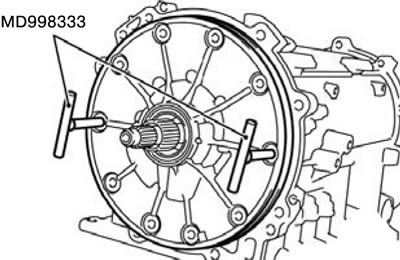
2) Install the special tool into the bolt hole as shown in the figure.
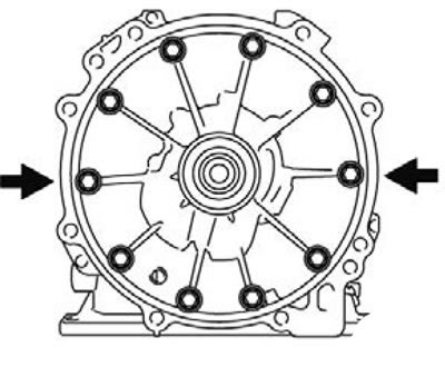
3) Remove the oil pump when the special tool MD998333 is fully screwed in.
52. Remove the oil pump gasket (52).
53. Remove thrust ring No. 1 (53).
54. Remove thrust bearing No. 2 (54).
55. Remove the return and overrunning clutch (55).
56. Remove thrust bearing No. 3 (56).
57. Remove the overrunning clutch sleeve (57).
58. Remove thrust bearing No. 4 (58).
59. Remove the return central gear (59).
60. Remove the spring ring (60).
61. Remove the secondary brake (61).
62. Remove the return spring (62).
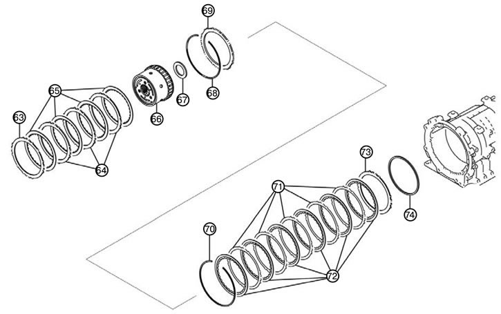
63. Remove the pressure plate (63).
64. Remove the brake disc (64).
65. Remove the brake disc (65).
66. Remove the return ring gear (66).
67. Remove thrust bearing No. 7 (67).
68. Remove the spring ring (68).
69. Remove the reaction disk (69).
70. Remove the spring ring (70).
71. Remove the brake disc (71).
72. Remove the brake disc (72).
73. Remove the pressure plate (73).
74. Remove the wave spring (74).
75. Remove the spring ring (75).
76. Remove the central support (76).
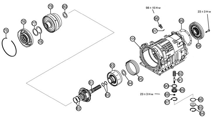
75. Remove the spring ring (75).
76. Remove the central support (76).
77. Remove thrust ring No. 8 (77).
78. Remove thrust bearing No. 9 (78).
79. Remove the direct acting ring gear (79).
80. Remove thrust bearing No. 12 (80).
81. Remove the direct acting planetary shaft (81).
82. Remove the sealing ring (82).
83. Remove the sealing ring (83).
84. Remove the spring ring (84).
85. Remove the reduction brake cover (85).
86. Remove the sealing ring (86).
87. Remove the spring ring (87).
88. Remove the reduction brake piston nut (88).
89. Remove the reduction brake piston (89).
90. Remove the sealing ring (90).
91. Remove the adjusting rod of the reduction brake piston (91).
92. Remove the reduction brake spring (92).
93. Remove the direct acting coupling (93).
94. Remove thrust bearing No. 13 (94).
95. Remove the reduction brake connection (95).
96. Remove the anchor plug (96).
97. Remove the sealing ring (97).
98. Remove the output shaft support (98).
99. Remove the output shaft support gasket (99).
1) Loosen the eight output shaft support mounting bolts, and then remove the output shaft support and gasket
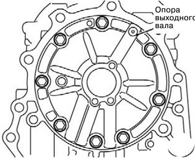
100. Remove the gearbox housing (100).