



Note: When assembling, tighten the bolts to the tightening torques shown in the figure.
1. Install the gearbox housing (100).
2. Install the output shaft support gasket (99).
3. Install the output shaft support (98).
1) Install a new gasket and output shaft support.
Caution: Never reuse an old gasket.
2) Tighten the eight output shaft support mounting bolts to the recommended tightening torque.
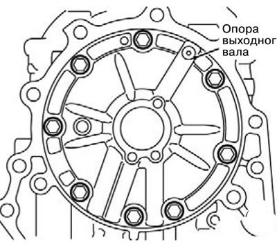
4. Install the sealing ring (97).
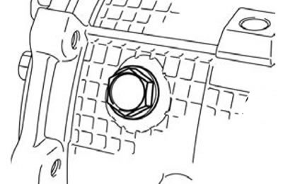
5. Install the anchor plug (96).
1) Install a new O-ring and anchor plug and tighten the anchor plug to the recommended tightening torque.
6. Install the reduction brake connection (95).
7. Install thrust bearing No. 13 (94).
Caution: Be careful not to confuse the installation direction of the thrust bearing.
Note: Install all thrust bearings and rings in accordance with the identification chart.
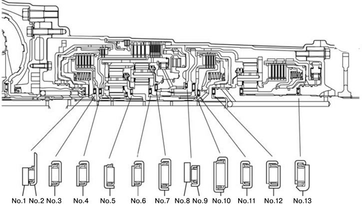
| Name | Outer diameter, mm | Inner diameter, mm | Thickness, mm |
| Nо.1 | 48.9 | 37 | 1.4 |
| 1.6 | |||
| 1.8 | |||
| 2.0 | |||
| 2.2 | |||
| 2.4 | |||
| 2.6 | |||
| No.2 | 59 | 37 | 2.8 |
| No.3 | 57 | 38.5 | 4.12 |
| No.4 | 57 | 38.5 | 4.12 |
| No.5 | 54.4 | 38.5 | 3.31 |
| No.6 | 57 | 38.5 | 4.12 |
| No.7 | 70 | 48.8 | 4.0 |
| No.8 | 73 | 60 | 1.6 |
| 1.8 | |||
| 2.0 | |||
| 2.2 | |||
| No.9 | 71.45 | 57 | 2.81 |
| No.10 | 72 | 48.25 | 4.6 |
| No.11 | 53 | 34.7 | 4.01 |
| No.12 | 57 | 38.5 | 4.12 |
| No.13 | 58 | 37.5 | 4.8 |
8. Install the direct acting coupling (93).
9. Install the reduction brake spring (92).
10. Install the adjusting rod of the reduction brake piston (91).
11. Install the sealing ring (90).
12. Install the reduction brake piston (89).
1) Install the reduction brake piston.
2) Adjust the reduction brake piston.
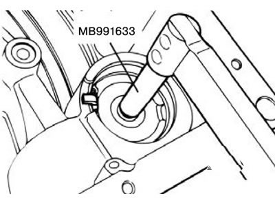
(1) Install the special tool so that the reduction brake piston does not rotate.
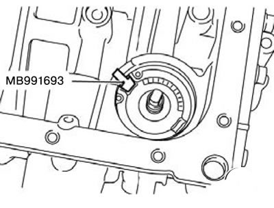
(2) Install the torque wrench on the special tool, tighten and loosen the special tool twice to the recommended tightening torque of 10 N·m, then tighten the adjusting rod of the reduction brake piston to the recommended tightening torque of 5 N·m. Turn the adjusting rod of the reduction brake piston 5 and 1/2 turns forward and 5 and 1/3 turns back.
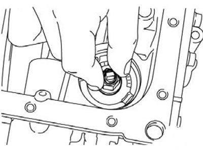
(3) Remove the special tool and hand tighten the reduction brake piston nut.
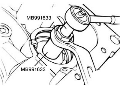
(4) Tighten the reduction brake piston nut to the recommended tightening torque of 19±3 N·m using a torque wrench.
13. Install the reduction brake piston nut (88).
14. Install the spring ring (87).
15. Install the sealing ring (86).
16. Install the reduction brake cover (85).
17. Install the spring ring (84).
18. Install the sealing ring (83).
19. Install the sealing ring (82).
20. Install the direct acting planetary shaft (81).
21. Install thrust bearing No. 12 (80).
Caution: Be careful not to confuse the installation direction of the thrust bearing.
22. Install the direct acting ring gear (79).
23. Install thrust bearing No. 9 (78).
24. Install thrust ring No. 8 (77).
Caution: Be careful not to confuse the installation direction of the thrust ring.
Caution: Measure and record the thickness of thrust ring #8 before installing it.
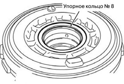
1) Apply petroleum jelly to thrust ring No. 8, and then install it onto the rear of the center support.
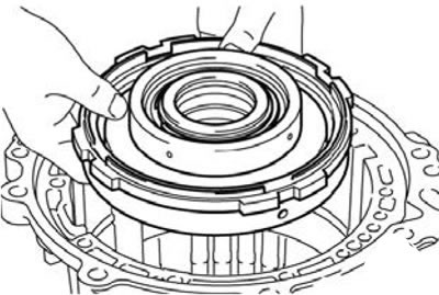
25. Install the central support (76).
Attention:
- Install the center support so that the oil hole faces the bottom of the gearbox housing as shown in the figure.
- Be careful not to let the thrust ring No. 8 installed at the rear of the central support fall out.
26. Install the spring ring (75).
27. Install the wave spring (74).
28. Install the pressure plate (73).
29. Install the brake disc (72).
30. Install the brake disc (71).
31. Install the spring ring (70).
32. Install the reaction disk (69).
33. Install the spring ring (68).
34. Install thrust bearing No. 7 (67).
Caution: Be careful not to confuse the installation direction of the thrust bearing.
35. Install the return ring gear (66).
36. Install the brake disc (65).
37. Install the brake disc (64).
38. Install the pressure plate (63).
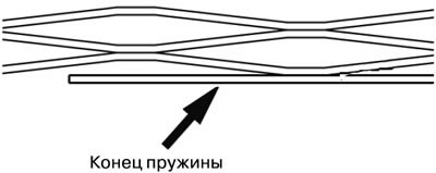
39. Install the return spring (62).
Caution: Install the return spring so that its flat part faces the rear of the gearbox.
40. Install the secondary brake (61).
41. Install the spring ring (60).
42. Install the return central gear (59).
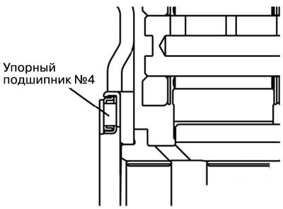
43. Install thrust bearing No. 4 (58).
Caution: Be careful not to confuse the installation direction of the thrust bearing.
1) Apply petroleum jelly to thrust bearing No. 4, and then install it onto the return center gear.
44. Install the overrunning clutch sleeve (57).
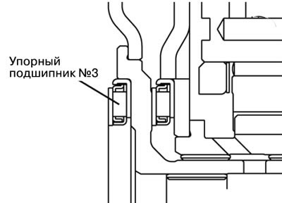
45. Install thrust bearing No. 3 (56).
Caution: Be careful not to confuse the installation direction of the thrust bearing.
1) Apply petroleum jelly to thrust bearing No. 3, and then install it onto the overrunning clutch sleeve.
46. Install the return and overrunning clutch (55).
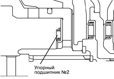
47. Install thrust bearing No. 2 (54).
Caution: Be careful not to confuse the installation direction of the thrust bearing.
1) Apply petroleum jelly to thrust bearing No. 2, and then install it onto the return and overrunning clutch.
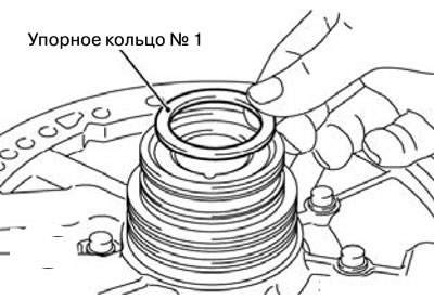
48. Install thrust ring No. 1 (53).
Caution: Be careful not to confuse the installation direction of the thrust ring.
1) Apply petroleum jelly to thrust ring No. 1, and then install it onto the oil pump.
49. Install the oil pump gasket (52).
Caution: Never reuse an old gasket.
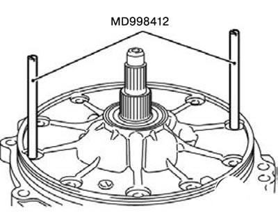
50. Install the oil pump (51).
1) Install the special tool MD998412 to the position shown in the figure, and use this guide to install the oil pump and oil pump gasket.
2) Tighten the ten oil pump mounting bolts to the recommended tightening torque.
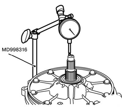
3) Install the digital indicator as shown in the figure using the special tool MD998316. Measure the axial clearance of the input shaft, and replace the thrust ring if the obtained value is outside the standard values.
Standard value: 0.25 - 0.81 mm.
4) Measure the axial clearance again and make sure it is within the standard values.
51. Install the torque converter housing (50).
1) Apply special grease to the torque converter housing.
Special grease: Mitsubishi Part No. MR166584 or equivalent.
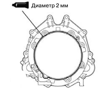
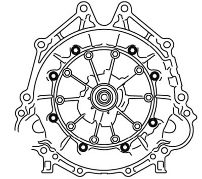
2) Install the torque converter housing.
3) Tighten the eight torque converter housing mounting bolts to the recommended tightening torque.
(The article is based on data from the website MitsubishiMan)
52. Install the parking roller rod (49).
53. Install the locking lever (48).
54. Install the sealing ring (47).
55. Install the sealing ring (46).
56. Install the manual control shaft (45).
57. Install the pin (44).
58. Install the spring pin (43).
59. Install the sealing ring (42).
60. Install the hydraulic accumulator piston (41).
61. Install the hydraulic accumulator piston (40).
62. Install the hydraulic accumulator spring (39).
63. Install the sealing ring (38).
64. Install the accumulator cover (37).
65. Install the spring ring (36).
66. Install the outer spring (35).
67. Install the inner spring (34).
68. Install the hydraulic accumulator piston (33).
69. Install the outer spring (32).
70. Install the inner spring (31).
71. Install the hydraulic accumulator piston (30).
72. Install the outer spring (29).
73. Install the inner spring (28).
74. Install the hydraulic accumulator piston (27).
75. Install the hydraulic accumulator spring (26).
76. Install the hydraulic accumulator piston (25).
77. Install the sealing ring (24).
78. Install the oil filter (23).
79. Install the oil seal (22).
80. Install the oil seal (21).
81. Install the solenoid valve wiring (20).
82. Install the spring ring (19).
83. Install the sealing ring (18).
84. Install the valve body (17).
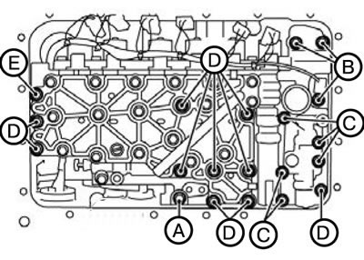
1) Tighten the twenty valve body mounting bolts to the recommended tightening torque.
| Bolt | Length, mm |
| A | 25 |
| IN | 30 |
| WITH | 40 |
| D | 45 |
| E | 55 |
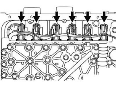
2) Connect the connectors to the valve body.
85. Install the locking spring (16).
86. Install the sealing ring (15).
87. Install the oil filter (14).
1) Tighten the oil filter mounting bolt to the recommended tightening torque.
Tightening torque: 6.0±1.0 Nm.
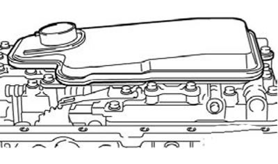
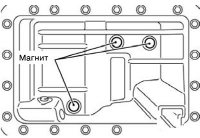
88. Install the magnet (13).
1) Install three magnets.
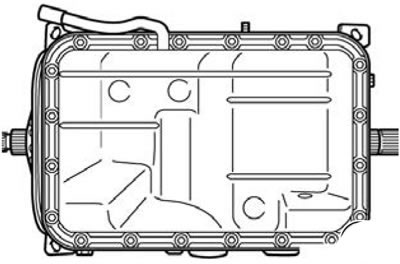
89.Install the oil pan (12).
1) Apply special grease to the oil pan.
Special lubricant: genuine MITSUBISHI sealant No. MR166584 or equivalent.
2) Install the oil pan.
3) Tighten the oil pan mounting bolts to the recommended tightening torque.
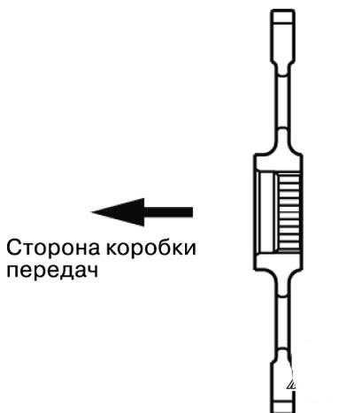
90. Install the parking gear (11).
1) Install the parking gear as shown in the figure.
91. Install the spring ring (10).
92. Install the park/neutral switch (9).
93. Install the manual control lever (8).
94. Install the output shaft speed sensor (7).
95. Install the input shaft speed sensor (6).
96. Install the electrical wiring bracket (5).
97. Install the clamp (4).
98. Install the clamp (3).
99. Install the cable end bracket (2).
100. Install the torque converter (1).