



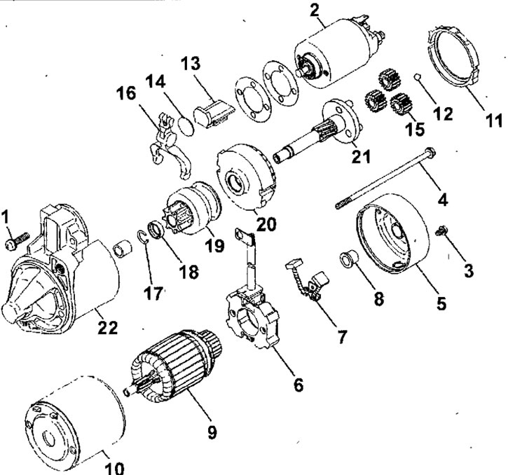
Fig. 19.40. Engine starter 4G9: 1 - screw; 2 - traction relay; 3 - screw; 4 - tension bolt; 5 - back cover; 6 - brush holder; 7 - brush; 8 - rear bearing; 9 - anchor; 10 - stator; 11 - Gasket A; 12 - ball; 13 - Gasket B; 14 - plate, 15 - planetary gear satellites; 16 - lever; 17 - retaining ring; 18 - thrust ring; 19 - freewheel clutch; 20 - crown gear; 21 - sun gear; 22 - front cover
Engine starter 4G9
Disassembly
- Disconnect the excitation coil wire from terminal M of the traction relay (Fig. 19.41).
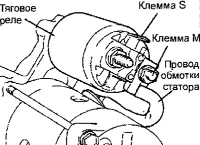
Fig. 19.41. Location of contacts of the traction relay of the 4G9 engine starter
- Remove the screws and remove the traction relay.
- Remove the gasket and plate
- Remove the screws and remove the back cover.
- Remove the rear bearing.
- Remove the brush holder assembly
- Remove the stator assembly with the winding.
- Remove the starter anchor. When removing the anchor, do not lose the ball located at the end of the shaft.
- Remove the drive lever.
- Using a suitable socket head, push the thrust ring down (Fig. 19.42).
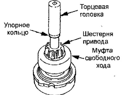
Fig. 19.42. Downward movement of the thrust ring
- Using special pliers, remove the retaining ring, then the thrust ring and the freewheel clutch (Fig. 19.43).
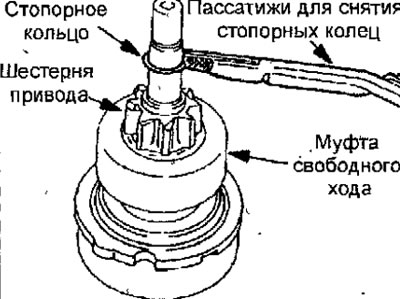
Fig. 19.43. Removing the retaining ring
Checking the collector
- Install the rotor on V-shaped supports and use a pointer-type indicator to check the ovality of the collector (Fig. 19.44).
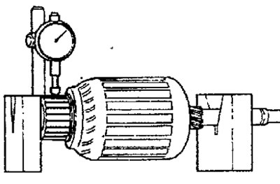
Fig. 19.44. Checking the ovality of the collector
Collector ovality:
- nominal: 0.05 mm
- maximum permissible: 0.1 mm
- Use a caliper to measure the outside diameter of the manifold (Fig. 19.45).
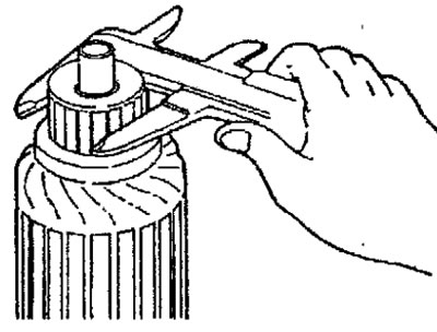
Fig. 19.45. Measuring the outside diameter of the manifold
Starter manifold outer diameter with reduction gear:
- nominal: 32.0 mm
- minimum allowable: 31.0 mm
Collector outer diameter:
- nominal: 29.4 mm
- minimum allowable: 28.4 mm
- Measure the protrusion of the collector plates from the insulation (Fig. 19.46).
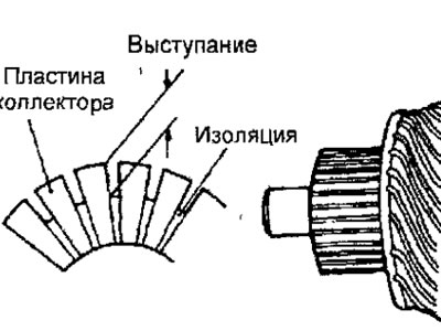
Fig. 19.46. The place of measurement of the protrusion of the collector plates from the insulation
Protrusion of collector plates from insulation:
- nominal: 0.5 mm
- minimum allowable: 0.2 mm
Checking the freewheel clutch
- Check the condition of the freewheel clutch gear teeth and replace them if damaged. Also check the condition of the flywheel ring gear teeth.
- Turn the gear. The gear should turn freely clockwise and lock when turned counterclockwise (Fig. 19.47).
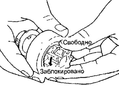
Fig. 19.47. Checking the freewheel clutch
Replacing the brush and spring
- Check the brushes for roughness of the surface in contact with the commutator and Check the length of the brushes. Replace brushes worn below the limit line (Fig. 19.48).
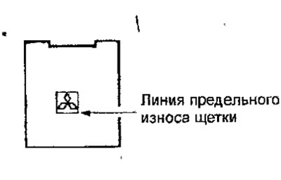
Fig. 19.48. Location of the starter brush wear limit line
- If the surface in contact with the commutator has been mechanically corrected, insert fine-grained sandpaper between the brushes and the commutator, with the abrasive layer of the paper facing the brushes, and, rotating the commutator, grind the brushes so that their contour matches the contour of the commutator.
Checking the rotor winding
- Check the rotor winding with a special device (Fig. 19.49). If there are short circuits in the rotor winding, replace the rotor. If the steel strip applied to the rotor vibrates, then there are short circuits in the rotor windings.
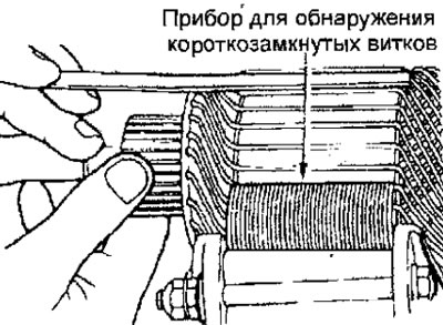
Fig. 19.49. Checking the rotor winding for short-circuited turns
- Use an ohmmeter to check the conductivity between the collector and the rotor (Fig. 19.50). If there is conductivity, replace the rotor.
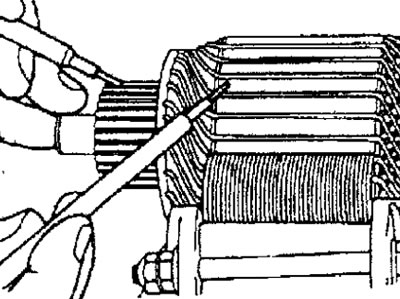
Fig. 19.50. Checking the conductivity between the collector and the rotor
- Use an ohmmeter to check the conductivity between the collector plates (Fig. 19.51). If there is no conductivity, replace the rotor.
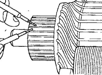
Fig. 19.51. Checking the conductivity between the collector plates
Assembly
- The starter assembly is carried out in the reverse order of disassembly, taking into account the following.
- Using a special tool, install the thrust ring and the freewheel clutch retaining ring from the front side of the rotor shaft, then move the thrust ring toward the retaining ring (Fig. 19.52).
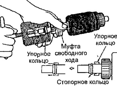
Fig. 19.52. Installing the thrust and retaining rings
Engine starter 4G1
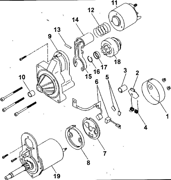
Fig. 19.53. Engine starter 4G1: 1 - back cover; 2- rubber gasket; 3 - protective cover; 4 - brush spring; 5 - contact plates; 6 - brush; 7 - brush holder; 8 - sealing insert; 9 - front cover; 10 - bearing sleeve; 11 - traction relay; 12-spring; 13-axis drive lever; 14-core; 15 - drive lever; 16 - retaining ring; 17 - limiting ring; 18 - freewheel clutch; 19 - starter motor
Disassembly
- Unscrew the nuts and remove the back cover.
- Remove the rubber gasket.
- Remove the protective cover.
- Remove the brush spring.
- Remove the contact plates.
- Remove the brushes.
- Remove the brush holder and sealing insert.
- Remove the bolts and remove the front cover.
- Remove the bearing sleeve.
- Remove the screws and remove the traction relay.
- Remove the spring.
- Knock out the drive lever axle.
- Remove the core.
- Remove the drive lever.
- Using a suitable socket head, push the thrust ring down (Fig. 19.54).
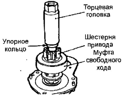
Fig. 19.54. Downward movement of the thrust ring
- Using special pliers, remove the retaining ring, then the thrust ring and the freewheel clutch (Fig. 19.55).
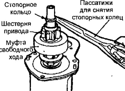
Fig. 19.55. Removing the retaining ring
Checking the freewheel clutch
- Check the condition of the freewheel clutch gear teeth and replace them if damaged. Also check the condition of the flywheel ring gear teeth.
- Turn the gear. The gear should turn freely clockwise and lock when turned counterclockwise (see Fig. 19.47).
Checking the commutator brushes
- Measure the length of the brush, which should be at least 11 mm (Fig. 19.56).
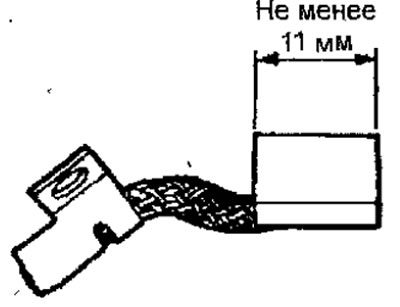
Fig. 19.56. Location for measuring the length of the commutator brush
Assembly
- The starter assembly is carried out in the reverse order of disassembly, taking into account the following.
- Using the special tool, install the thrust ring and the overrunning clutch retaining ring from the front side of the rotor shaft, then move the thrust ring toward the retaining ring (see Fig. 19.52).
Engine starter 4G18
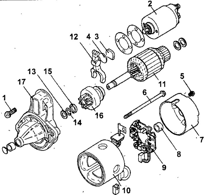
Fig. 19.57. 4G18 engine starter with direct transmission: 1 - screw; 2 - traction relay; 3 - gasket; 4 - plate; 5 - screw; 6 - tension bolt; 7 - rear cover; 8 - rear bearing: 9 - brush holder assembly; 10 - stator; 11 - starter anchor; 12 - drive lever; 13 - washer; 14 - retaining ring; 15 - thrust ring; 16 - freewheel clutch; 17 - front cover
Disassembly
- Remove the screws and remove the traction relay.
- Remove the gasket and plate.
- Remove the screws and remove the back cover.
- Remove the tie bolts.
- Lower the rear bearing.
- Remove the brush holder assembly.
- Remove the stator.
- Remove the starter armature.
- Remove the drive lever.
- Remove the washer.
- Using a suitable socket head, push the thrust ring down (see Fig. 19.42).
- Using special pliers, remove the retaining ring, then the thrust ring and the freewheel clutch (see Fig. 19.43).
Assembly
- The starter assembly is carried out in the reverse order of disassembly, taking into account the following.
- Using a special tool, install the thrust ring and the freewheel clutch retaining ring from the front side of the rotor shaft, then move the thrust ring toward the retaining ring (see Fig. 19.52).