



Contents: Checking and adjusting the axial…⤓ Checking the pull-in traction…⤓ Checking the holding winding of the…⤓ Idle performance tests ⤓
Checking and adjusting the axial clearance of the gear
- Disconnect the excitation coil wire from terminal M of the traction relay.
- Using additional wires, connect the battery terminals to terminals S and M (Fig. 19.29).
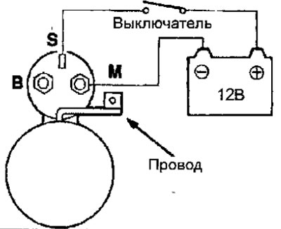
Fig. 19.29. Starter connection diagram for checking and adjusting the axial clearance of the gear
- Turn the ignition switch key to the ON position, the drive pinion will extend to the stop. This check must be completed within 10 seconds, otherwise the traction relay coil may burn out.
- Use a feeler gauge to check the gap between the gear and the stopper (Fig. 19.30).
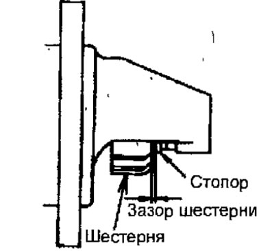
Fig. 19.30. Checking the starter gear clearance
Gear clearance: 0.5-0.2 mm
- If the gap differs from the required one, adjust it by adding or removing shims between the traction relay and the front cover (Fig. 19.31).
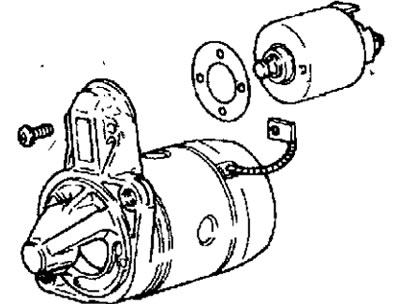
Fig. 19.31. Gasket installation location when adjusting the starter gear clearance
Checking the pull-in traction winding of the relay
- Disconnect the excitation coil wire from terminal M of the traction relay.
- Using additional wires, connect the battery terminals to terminals S and M (Fig. 19.32, 19.33). This check must be performed within 10 seconds, otherwise the traction relay coil may burn out.
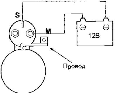
Fig. 19.32. Starter connection diagram when checking the traction relay of the 4G9 engine starter
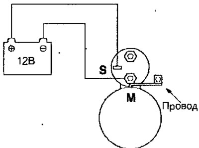
Fig. 19.33. Starter connection diagram when checking the traction relay of the 4G1 engine starter
- If the drive pinion extends, the pull-in winding is OK. If the pinion does not extend, replace the traction relay.
Checking the holding winding of the traction relay
- Disconnect the excitation coil wire from terminal M of the traction relay.
- Using additional wires, connect the battery terminals to terminal S and the traction relay housing (Fig. 19.34). This check must be performed within 10 seconds, otherwise the traction relay coil may burn out.
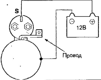
Fig. 19.34. Starter connection diagram when checking the holding winding of the traction relay of the 4G9 engine
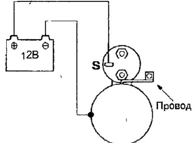
Fig. 19.35. Starter connection diagram when checking the holding winding of the traction relay of the 4G1 engine
- Manually extend the drive gear until it stops.
- If the drive pinion remains in the extended position, the holding winding is OK. If the pinion retracts, there is a break in the holding winding. In this case, replace the traction relay.
Idle performance tests
- To perform idle tests, secure the starter in a vice with soft jaws and connect the wires from a fully charged battery to its terminals as follows (Fig. 19.36, 19.37).
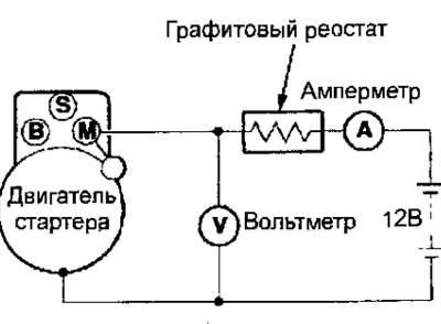
Fig. 19.36. Connection diagram for performance testing of the 4G9 and 4G18 engine starter
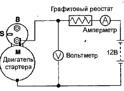
Fig. 19.37. Connection diagram for performance testing of the 4G1 engine starter
- Set the graphite rheostat slider to a position where the voltmeter shows 11.0 V, while checking the current consumed by the starter and making sure that the starter shaft turns easily and smoothly.
Current:
- engine starter 4G9: no more than 50 A
- engine starter 4G1: no more than 40 A
- engine starter 4G18: no more than 60 A
- Disconnect the excitation coil wire from terminal M of the traction relay.
- Using additional wires, connect the battery terminals to terminal M and the traction relay housing (Fig. 19.38, 19.39). This check must be performed within 10 seconds, otherwise the traction relay coil may burn out.
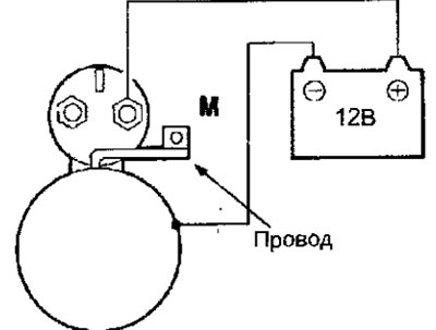
Fig. 19.38. Connection diagram for checking the return of the anchor of the traction relay of the 4G9 engine starter
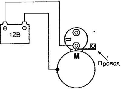
Fig. 19.39. Connection diagram for checking the return of the anchor of the traction relay of the 4G1 engine starter
The starter pinion should move forward. After disconnecting the wires, the starter pinion should quickly return to its original position. Otherwise, replace the solenoid relay.