
4G9 gasoline engine generator repair
Disassembly
- Secure the generator in a vise.
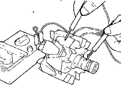
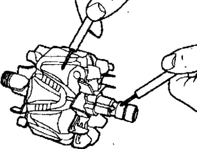
- Remove the four tie bolts, insert the blade of two flat screwdrivers between the front cover and the stator magnetic circuit, press the screwdrivers and remove the cover (pic. 19.9). Do not insert screwdrivers too deep as the stator winding may be damaged.
Pic. 19.9. Using two screwdrivers to remove the front cover of the generator
- Secure the rotor in a vise on the pulley side, being careful not to damage the rotor.
- Unscrew the pulley mounting nut, and remove the spring washer and pulley (pic. 19.10).
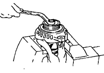
Pic. 19.10. Unscrewing the nut securing the alternator pulley
- Remove the front cover and two washers.
- Remove the rotor from the vise.
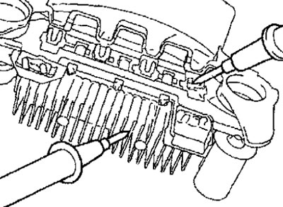
- Remove the screws securing the brush holder, rectifier and terminal B nuts.
- Remove the stator from the rear cover.
- Separate the oil deflector from the brush holder.
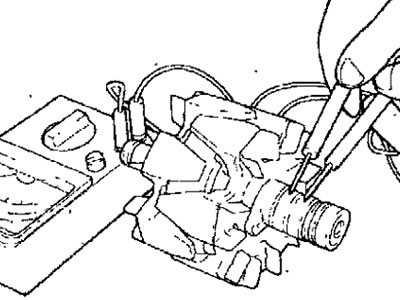
- With a soldering iron with a power of 180-250 W, unsolder the wires from the diodes and remove the stator. When desoldering, make sure that heat from the soldering iron is not transferred to the rectifier diodes. Desoldering should be carried out as soon as possible, otherwise the rectifier diodes may be damaged.
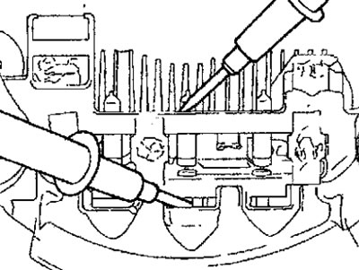
- When separating the rectifier from the voltage regulator, desolder the wires soldered to the rectifier (pic. 19.11).
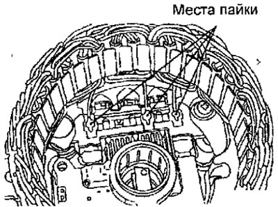
Pic. 19.11. Places for soldering wires when removing the stator
Rotor check
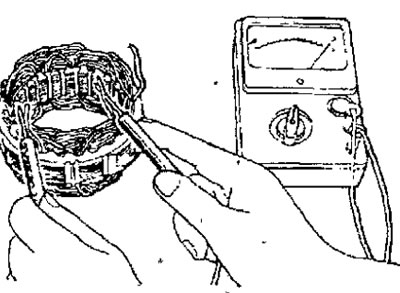
- Measure the resistance between the slip rings with an ohmmeter (pic. 19.12). If the resistance is not as required, replace the rotor.
Pic. 19.12. Resistance measurement between rotor slip rings
Resistance: 2-5 ohm
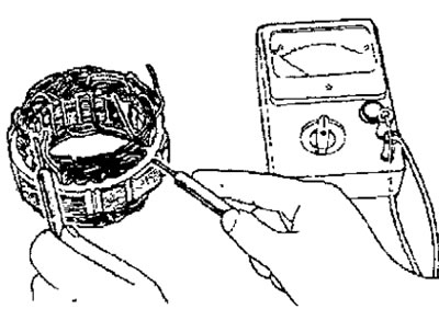
- Using an ohmmeter, check the continuity between the slip ring and the armature of the rotor (pic. 19.13). If there is continuity, replace the rotor.
Pic. 19.13. Resistance measurement between slip ring and rotor armature
Stator check
- Using an ohmmeter, check the continuity between the terminals of the stator coil (pic. 19.14). If there is no continuity, replace the stator.
Pic. 19.14. Resistance measurement between stator coil terminals
- Using an ohmmeter, check the continuity between each winding terminal and the stator core (pic. 19.15). If there is continuity, replace the stator.
Pic. 19.15. Measuring the resistance between each winding terminal and the stator core
Rectifier test
- Make sure there is a circuit between the positive poles of the rectifier and the stator coil lead terminal (pic. 19.16). The ohmmeter should only show conductivity in one direction. If there is conductivity in both directions, then the diode is broken and the rectifier must be replaced.
Pic. 19.16. Conductivity measurement between the positive poles of the rectifier and the stator coil lead terminal
- Ensure there is an open circuit between the negative poles of the rectifier and the stator coil lead terminal (pic. 19.17). The ohmmeter should only show conductivity in one direction. If there is conductivity in both directions, then the diode is broken and the rectifier must be replaced.
Pic. 19.17. Resistance measurement between the negative poles of the rectifier and the stator coil terminal
- Using an ohmmeter, check the continuity between the terminals of each of the three diodes (pic. 19.18). The ohmmeter should only show conductivity in one direction. If there is conductivity in both directions, then the diode is broken and the rectifier must be replaced.
Pic. 19.18. Measuring the resistance between the terminals of each of the three diodes
Checking the brushes
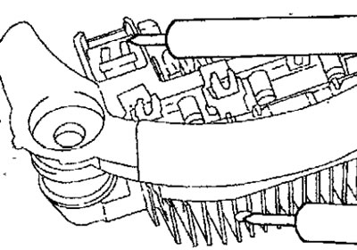
- Measure the brush protrusion and replace the brush if the brush protrusion is less than 2mm (pic. 19.19).
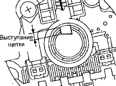
Pic. 19.19. Brush protrusion measuring point
- Unsolder the braided wire and remove the spring and brush (pic. 19.20).
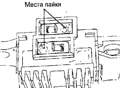
Pic. 19.20. Place of soldering braided brush wires
- Install the brush spring and new brush into the brush holder.
- Insert the brush so that there is a distance of 2-3 mm between the wear limit line and the end face of the brush holder.
- Solder the braided wire to the brush holder.
Assembly
- Assembly is carried out in the reverse order of disassembly, taking into account the following.
- After installing the voltage regulator, before attaching the rotor to the back cover, insert a wire through the small hole in the back cover to lock the brushes in the retracted position (pic. 19.21). After installing the rotor, remove the wire.
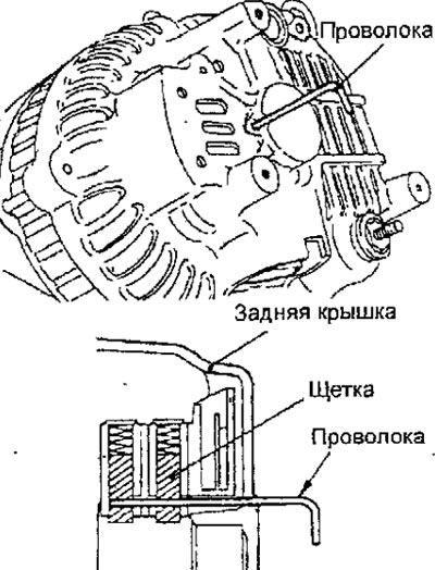
Pic. 19.21. Installing the wire to fix the brushes in the retracted position
4G1 gasoline engine generator repair
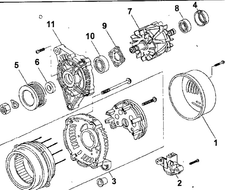
Pic. 19.22. 4G1 gasoline engine alternator:1 - rear protective cover of the generator: 2 - brush holder assembly; 3 - stator and rectifier; 4 - bearing cover; 5 - generator pulley; 6 - remote washer; 7 - rotor assembly; 8 - rear bearing: 9 - bearing holder; 10 - front bearing; 11 - front cover
Disassembly
- Turn out screws and remove a back protective cover of the generator.
- Remove the screws and remove the brush holder.
- Remove the screws and remove the stator and rectifier.
- Remove the bearing cap.
- Secure the front cover of the generator in a soft jaw vise.
- Use a hex wrench to hold the rotor shaft from turning and loosen the nut (pic. 19.23). Loosen the nut and remove the pulley.
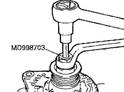
Pic. 19.23. Using a hex wrench to hold the rotor shaft from turning and loosening the pulley mounting nut
- Remove spacer.
- Remove the rotor assembly.
- Remove the rear bearing.
- Remove the bearing holder.
- Remove the front bearing.
Rotor check
- Check for an open in the rotor winding. Check for continuity between the slip rings of the generator rotor (pic. 19.24). If there is too little resistance (tends to 0), it means there is a short circuit. In the event of an open or short circuit in the rotor winding circuit, replace the rotor assembly.
Pic. 19.24. Checking the conductivity between the slip rings of the generator rotor
Resistance: 2.6 ohm
- Check for a short circuit between the rotor winding and the rotor core (pic. 19.25). Check that there is no continuity between slip ring and core. If the circuit is shorted, replace the rotor.
Pic. 19.25. Checking the absence of a short circuit between the slip ring and the rotor core
Stator check
- Check for open circuits in the stator windings. Check that there is no open circuit between the terminals (A) - (IN), (WITH) - (D) And (E) - (F) (pic. 19.26).
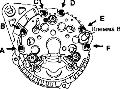
Pic. 19.26. Location of stator windings
- Check that the stator windings are not shorted to the stator core. Make sure that the circuit between each stator winding terminal and the core is open. If the circuit is shorted, replace the stator and rectifier.
Rectifier test
- Check continuity between terminal B and stator winding leads (A), (WITH) And (E) (see fig. 19.26). A short circuit in both directions means a breakdown of the diode, so the stator and rectifier must be replaced.
- Check continuity between stator winding leads (IN), (D), (F) And «weight». A short circuit in both directions means a breakdown of the diode, therefore it is necessary to replace the stator and rectifier
Brush replacement
- If the brush has worn to the center of the mark (3 mm from the center of the brush holder), replace the brush holder (pic. 19.27).
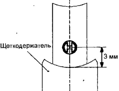
Pic. 19.27. Checking the wear of the alternator brushes
Assembly
- Assembly is carried out in the reverse order of removal.