



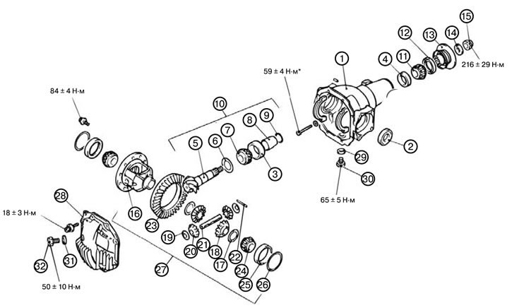
Caution: * Indicates parts that must be pre-tightened and then finally tightened with the unloaded vehicle on its wheels on a level, flat surface.
Note: When installing, tighten the bolts to the torques shown in the figure.
1. Install the differential cup (1).
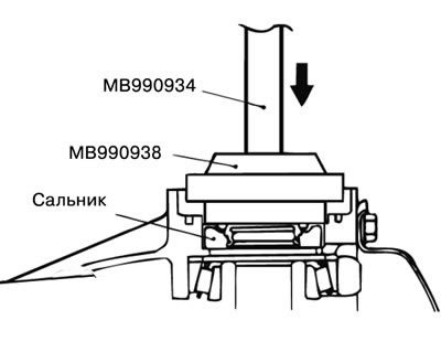
2. Install the seal (2).
1) Install the oil seal using the special tool MB990938 and special tool MB990934, and then apply grease to the lip of the oil seal.
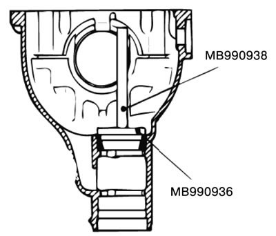
3. Install the outer ring of the rear bearing of the drive shaft (3).
1) Install the outer ring of the rear bearing of the drive shaft into the differential cup using the special tool MB990938 and the special tool MB990936.
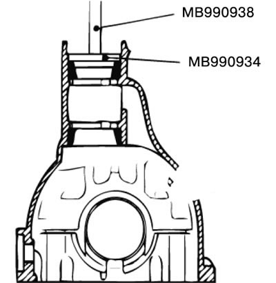
4. Install the outer ring of the front bearing of the drive shaft (4).
1) Install the outer ring of the front bearing of the drive shaft into the differential cup using the special tool MB990938 and the special tool MB990934.
5. Adjust the height of the drive shaft.
1) Apply grease to the washer of the special tool MB990819.
2) Install the special tool, the inner ring of the front and rear bearings of the drive shaft into the differential cup.
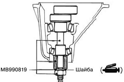
3) Tighten the nut of the special tool MB990819 using a torque wrench until the tightening torque is within the permissible values.
Standard value: 0.83 - 1.19 Nm.
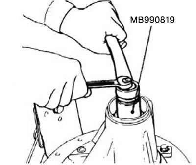
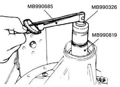
4) Clean the side bearing bushing.
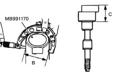
5) Install the special tool MB991170 and special tool MB990819 into the side bearing of the differential cup, and position the groove as shown in the figure. Then install the bearing caps.
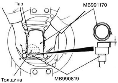
6) Measure the gap (A) between the special tools using a thickness measuring device.
7) Remove special tools.
8) Measure the special tools in the places (B, C) shown in the figure using a micrometer.
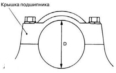
9) Install the bearing cap, and then measure the inner diameter (D) of the bearing cap as shown in the figure using a micrometer.
10) Calculate the thickness (E) of the drive shaft ring using the formula: E = A + B + C - 1/2D - 100.0 mm
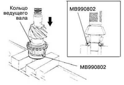
11) Install the selected drive shaft ring onto the drive shaft, and install the drive shaft front bearing inner ring using the special tool MB990802.
6. Install the drive shaft (5).
7. Install the rear ring of the drive shaft (to adjust the shaft height) (6).
8. Install the inner ring of the rear bearing of the drive shaft (7).
9. Install the drive shaft washer (8).
10. Adjust the shaft rotation torque.
1) Insert the drive shaft into the differential cup, and then install the drive shaft washer, drive shaft rear ring, drive shaft rear bearing inner ring, and coupling flange in this order.
Note: Do not install the oil seal.
2) Tighten the coupling flange lock nut to the recommended tightening torque while holding the coupling flange using the special tool MB990767.
Tightening torque: 216±29 Nm.
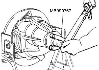
3) Measure the torque of the drive shaft (without seal) using a torque wrench.
Standard value: 0.83 - 1.19 Nm.
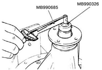
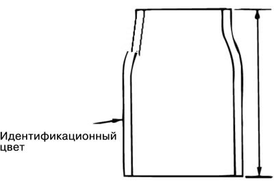
4) If the drive shaft torque is out of specification, replace the drive shaft rear ring or drive shaft washer.
| Height of drive shaft washer, mm | Identification color |
| 56,67 | White |
| 57,01 | - |
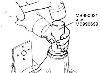
5) Remove the connecting flange and drive shaft. Then insert the inner ring of the front bearing of the drive shaft into the differential cup, then install the oil seal using the special tool MB990031 or MB990699.
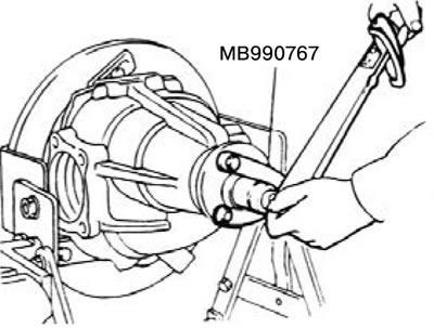
6) Install the drive shaft and connecting flange so that the alignment marks are aligned. Tighten the coupling flange lock nut to the recommended tightening torque while holding the coupling flange using the special tool MB990767.
Tightening torque: 216±29 Nm.
7) Measure the torque of the drive shaft (with gland) using a torque wrench.
Standard value: 0.93 - 1.28 Nm.
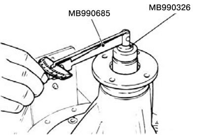
8) If the drive shaft torque is out of specification, check the tightening torque of the lock nut and the condition of the oil seal.
11. Install the front ring of the drive shaft (to adjust the torque) (9).
12. Install the drive shaft assembly (10).
13. Install the inner ring of the front bearing of the drive shaft (11).
14. Install the oil seal (12).
15. Install the connecting flange (13).
16. Install the washer (14).
17. Install the lock nut (15).
18. Install the differential housing (16).
19. Adjust the differential gear play.
1) Install the side gears, side gear washers, drive shafts and shaft washers into the differential housing.
2) Temporarily install the pinion shaft.
Note: Do not install the locking pin.
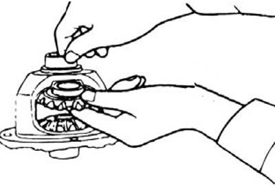
3) Insert a wedge between the side gear and the gear shaft to fix the side gear.
4) Measure the differential gear play using a digital indicator.
Standard value: 0.01 - 0.25 mm.

5) If the backlash value is out of specification, adjust it by replacing the side gear washers.
6) If adjustment is not possible, replace the side gears and gear shafts.
7) Measure the clearance again.
20. Install the side gear washer (17).
21. Install the side gear (18).
22. Install the shaft washer (19).
23. Install the drive gear (20).
24. Install the gear shaft (21).
25. Install the locking pin (22).
1) Align the locking pin hole of the drive shaft with the locking pin hole of the differential housing, and install the locking pin.
2) Secure the locking pin at two points using a punch.
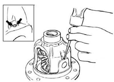
26. Install the drive gear (23).
1) Clean the pinion mounting bolts.
2) Clean the mounting holes of the drive gear with a tap (M10x1.25), and then clean the holes with compressed air.
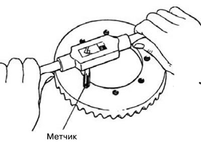
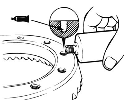
3) Apply special grease to the holes of the drive gear.
Special grease: LOCTITE No.271 or No.270.
4) Install the drive gear into the differential housing according to the installation marks. Tighten the bolts to the recommended torque in a diagonal direction.
Tightening torque: 84±4 Nm.
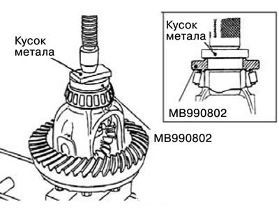
27. Install the inner ring of the side bearing (24).
1) Install the inner ring of the side bearing into the differential housing using the special tool MB990802.
28. Install the outer ring of the side bearing (25).
29. Adjust the play of the differential drive gear.
1) Install the side bearing washers onto the side bearing outer races, and then install the differential housing into the differential cup.
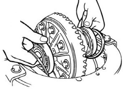
2) Move the differential housing to one side and measure the gap between the differential cup and the side bearing adjusting washer using a feeler gauge.
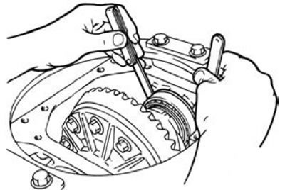
3) Measure the thickness of the side bearing adjusting washers.
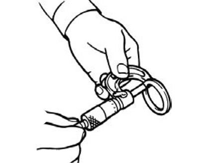
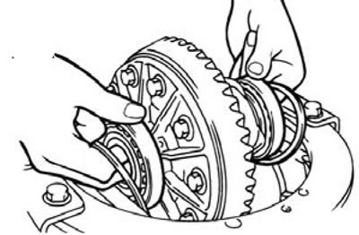
4) Install the side bearing adjusting washers and differential housing as shown in the figure into the differential cup.
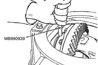
5) Install the side bearing adjusting washers into the special tool MB990939, and then install them onto the outer ring of the side bearing.
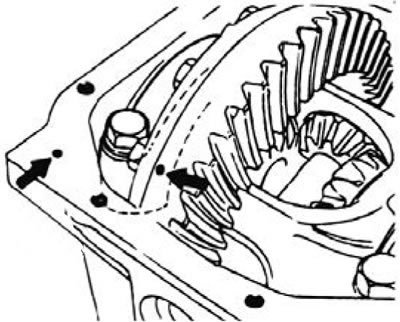
6) Align the timing marks on the differential cup and bearing cap, and then tighten the bearing cap.
Tightening torque: 59±4 Nm.
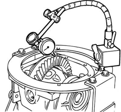
7) Measure the play of the drive gear using a digital indicator.
Standard value: 0.11 - 0.16 mm.
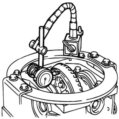
8) Measure the runout of the drive gear from the back side of the drive gear.
Limit value: 0.05 mm.
9) If the runout value is outside the permissible values, replace the drive gear and differential housing and take new measurements.
30. Install the side bearing washer (26).
31. Install the differential housing assembly (27).
32. Install the cover (28).
33. Install the seal (29).
34. Install the drain plug (30).
35. Install the gasket (31).
36. Install the filler plug (32).