
English Русский
Български
Беларускі
Український
Српски
Hrvatski
Română
Polski
Slovenský
Magyar
Articles Bookmark Contacts Sitemap   
Company Audi Company Ford Company Hyundai Company Kia Company Mazda Company Mercedes-Benz Company Nissan
MitsubishiMan.ru


Home Colt Lancer Galant L200 Outlander Pajero Others
Pajero 4 (2006-2021) Pajero 1 and 2 (1982-1999)

Disassembling the differential (Mitsubishi Pajero 4)

  • Home
  • Pajero
  • 4 (2006-2021)
  • Transmission
  • Drive shafts
  • Disassembling the differential
0


1. Conduct a check before disassembling.

1) Remove the cover and gasket.

2) Fix the special tool MB990909 and special tool MB991116 in a vice, and install the differential cup on the special tools.
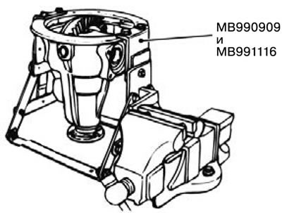


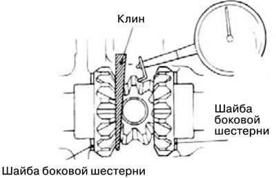
3) Check the play of the drive gear using a digital indicator.

Standard clearance: 0.11 - 0.15 mm.

If the pinion backlash value is not within the specification, it is necessary to install the thrust washer according to the specification above.
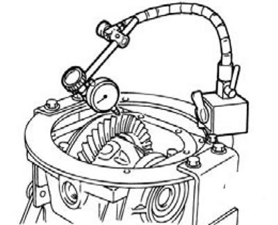


4) Check the radial runout of the drive gear using a digital indicator.


Standard size: 0.05 mm.

If the pinion radial runout value is not within specification, the pinion must be adjusted or the differential housing or pinion must be replaced.
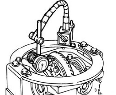


5) Check the side gear play using a digital indicator. Standard backlash: 0.01mm - 0.25mm. If the backlash value of the side gear is not within the specification, it is necessary to install the thrust washer according to the specification above.


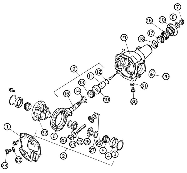
2. Remove the cover (1).

3. Remove the differential housing (2).

Caution: Be careful when removing the differential housing to avoid dropping it and damaging the washers and outer bearing races on the differential side.


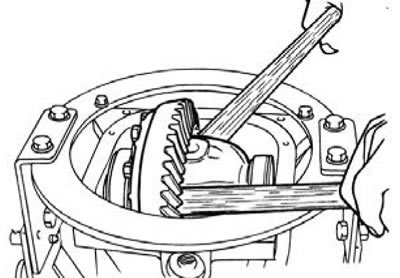
1) Remove the differential housing using a wooden hammer handle.

Note: Do not mix bearing shims when disassembling the differential.


4. Remove the side bearing washer (3).

5. Remove the outer ring of the side bearing (4).

6. Remove the inner ring of the side bearing (5).

1) When removing the inner ring of the side bearing, use the special tool MB990810 and the special tool MB990811.


7. Remove the drive gear (6).

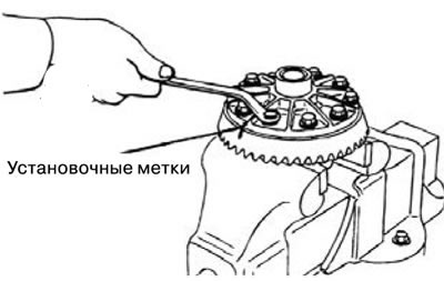
1) Apply timing marks to the differential housing and pinion gear.

2) Loosen the drive gear mounting bolts diagonally and remove the drive gear.


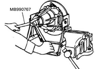
8. Return the lock nut (7).


1) Fix the connecting flange using the special tool MB990767, and then unscrew the lock nut.


9. Remove the washer (8).

10. Remove the drive shaft assembly (9).

Caution: The alignment marks on the connecting flange must be applied to the connecting surface of the flange and the front propeller shaft.


1) Apply alignment marks on the drive shaft and connecting flange.

2) Remove the drive shaft together with the special tool MB990810.


11. Remove the connecting flange (10).

12. Remove the drive shaft gasket (11).

13. Remove the front ring of the drive shaft (to adjust the torque) (12).

14. Remove the inner ring of the rear bearing of the drive shaft (13).

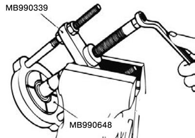
1) Remove the inner ring of the rear bearing of the drive shaft using special tool MB990339 and special tool MB990648.


The material is based on data from the website [MITSUBISHIMAN.ru]


15. Remove the rear ring of the drive shaft (to adjust the shaft height) (14).

16. Remove the drive shaft (15).

17. Remove the oil seal (16).

18. Remove the inner ring of the front bearing of the drive shaft (17).

19. Remove the outer ring of the front bearing of the drive shaft (18).

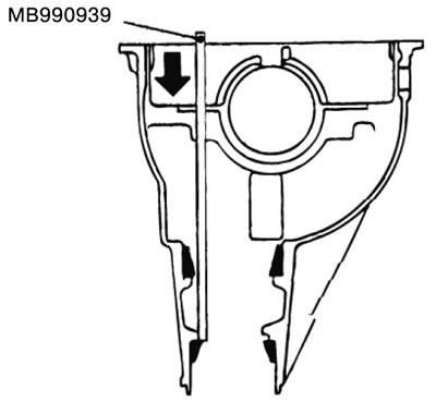
1) Remove the outer ring of the front bearing of the drive shaft using special tool MB990339.


20. Remove the outer ring of the rear bearing of the drive shaft (19).

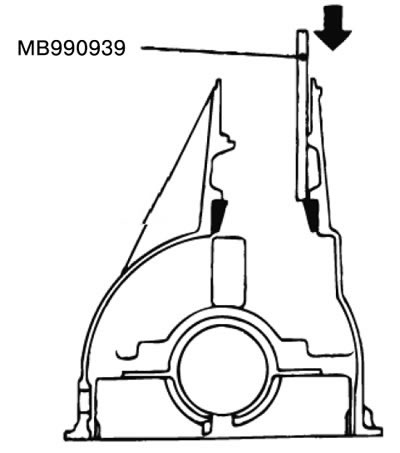
1) Remove the outer ring of the rear bearing of the drive shaft using special tool MB990939.


21. Remove the oil seal (20).


22. Remove the differential cup (21).

23. Remove the locking pin (22).

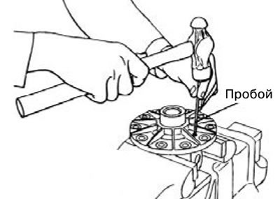
1) Remove the locking pin using a punch.

24. Remove the gear shaft (23).


25. Remove the drive gear (24).

26. Remove the gear washer (25).

27. Remove the side gear (26).

28. Remove the side gear washer (27).

29. Remove the filler plug (28).

30. Remove the gasket (29).

31. Remove the drain plug (30).

32. Remove the seal (31).

33. Remove the differential housing (32).
This article is available at: russian, bulgarian, belarusian, ukrainian, serbian, croatian, romanian, polish, slovak, hungarian
This article was reviewed by: Miroslav Rakov
Share with friends:
◀ Previous
Pajero 4: Drive shafts
Next ▶

Overrunning clutch
Installing the differential housing and overrunning clutch
Removal the differential housing and overrunning clutch
Assembly of the inner shaft
Disassembling the inner shaft
Differential assembly
Solenoid valve and vacuum hose
Front Differential Mount
Removal the rear axle hub
Installing the rear axle hub
Similar materials for other Mitsubishi models

➤ Differential box F5M21 — disassembly and assembly Mitsubishi Colt 4 and 5 (1991-2003)
➤ Differential Gearbox: Checking Oil Level Mitsubishi Lancer 3 and 5 (1984-1992)
➤ Replacing ATF automatic transmission and differential final… Mitsubishi Galant 6 and 7 (1987-1998)
➤ Disassembling the rear axle differential with locking… Mitsubishi L200 4 (2005-2014, diesel)
➤ Changing the oil in the differential of the front and rear… Mitsubishi Outlander 1 (2003-2008)
➤ Disassembling and assembling the gear shift lever Mitsubishi Carisma (1995-2004)
Link in different formats to this article
Comments and feedback from visitors
No comments yet


Add up two numbers 34 + 40


Pajero 4 (2006-2021) 
  • General information
  • User manual
  • Troubleshooting
  • Maintenance
  • Technical specifications
  • Power unit
  • Engine repair
  • Cooling system
  • Lubrication system
  • Fuel system
  • Engine management system
  • Intake and exhaust system
  • Engine electrical equipment
  • Transmission
  • Clutch
  • Manual gearbox
  • Automatic gearbox
  • Drive shafts
  • Chassis and running gear
  • Front suspension
  • Rear suspension
  • Brake system
  • Steering
  • Body and interior
  • Exterior (external elements)
  • Interior (internal elements)
  • Doors, locks and windows
  • Body dimensions
  • Electrical equipment
  • Safety system (SRS)
  • Air conditioner
  • Equipment and devices
  • Electrical diagrams
Pajero 1 and 2 (1982-1999) 
  • General information
  • User manual
  • Seats and seat belts
  • Instruments and controls
  • Driving and operation
  • Maintenance
  • Power unit
  • Gasoline engines
  • Diesel engines
  • Ignition system
  • Engine electrical equipment
  • Cooling and lubrication system
  • Power and exhaust system
  • Fuel system (gasoline)
  • Fuel system (diesel)
  • Transmission
  • Clutch
  • Mechanical gearbox
  • Automatic gearbox
  • Drive shafts and axles
  • Chassis and running gear
  • Front suspension
  • Rear suspension
  • Steering
  • Brake system
  • Body and interior
  • Exterior (external elements)
  • Interior (internal elements)
  • Doors, locks and windows
  • Electrical equipment
  • Equipment and devices
  • Heater and air conditioner
  • Cruise control
  • Headlights and lighting
  • Electrical circuits
MitsubishiMan.ru © 2018–2026 • Mobile version • Articles about Mitsubishi • Contacts • Sitemap: EN BG BY UA RS HR RO PL SK HU • Site search • Bookmark
Colt 2 and 3 (1983-1993) · Colt 4 and 5 (1991-2003) · Colt 5 (1995-2003) · Lancer 3 and 5 (1984-1992) · Lancer 9 (2000-2007) · Galant 5 (1983-1989) · Galant 6 and 7 (1987-1998) · L200 4 (2005-2014) · Outlander 1 (2003-2008) · Pajero 1 and 2 (1982-1999) · Pajero 4 (2006-2021) · Carisma (1995-2004) · Space Star (1998-2005) ·
This resource sets cookies 🍪 to avoid bothering you with repeated data entry.