



Caution! To disassemble the rear strut, you must use a spring compressor.
Disassembly
To disassemble the rear pillar, perform the following operations.
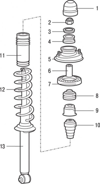
Fig. 16.17. Rear suspension strut: 1 – protective cap; 2 – self-locking nut (25 Nm); 3 – washer; 4 – upper bushing "B"; 5 – upper support of the rack; 6 – sleeve; 7 – upper spring cup; 8 – upper bushing "A"; 9 – shock absorber cup; 10 – compression stroke buffer; 11 – protective cover; 12 – spring; 13 – shock absorber assembly
1. Using a screwdriver blade as a lever, remove the protective cap 1 (Fig. 16.17).
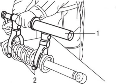
Fig. 16.18. Using special devices MB991239 (1) and MB991237 (2) to compress the spring
2. Using the special device МВ991239 1 (Fig. 16.18) with grips МВ991237, compress the spring so that it moves away from the upper cup. When using the special device for compressing springs, make sure that the spring turns are securely gripped and compress the spring from opposite sides. The spring has a very high compression force, so use a reliable tool. Never tie the spring with wire.
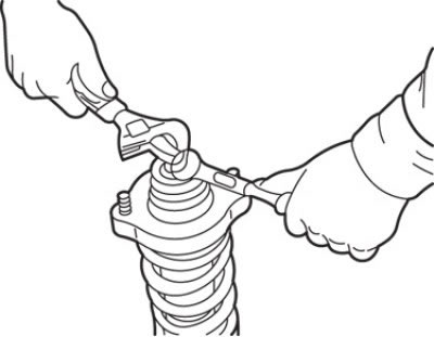
Fig. 16.19. Unscrewing the self-locking nut securing the shock absorber rod
3. Use a wrench to prevent the shock absorber rod from turning and, using a second wrench, unscrew the self-locking nut securing the shock absorber rod (Fig. 16.19).
Caution: Do not use an impact wrench to loosen the self-locking nut.
4. Remove washer 3 (see Fig. 16.17)
5. Remove the upper bushing "B" 4.
6. Remove the upper support of the 5th pillar.
[The text of the article was obtained from the website MitsubishiMan.ru]
7. Remove the upper cup 7 of the spring.
8. Remove the upper bushing "A" 8.
9. Remove sleeve 6.
10. Remove the shock absorber cup 9.
11. Remove the protective cover 11.
12. Remove the 10th compression stroke buffer.
13. Remove spring 12 together with the spring compressor.
Examination
1. Check rubber parts for damage.
2. Check the rear suspension springs for wear, cracks or damage.
3. Check the shock absorber for shock absorber fluid leaks. Check the entire length of the shock absorber rod for pitting corrosion and the shock absorber body for mechanical damage. Set the shock absorber in a vertical position and check its operation by moving the shock absorber rod through its full stroke. The shock absorber rod should move smoothly, with noticeable resistance. If the shock absorber rod moves jerkily or there is mechanical damage, the shock absorber must be replaced.
Assembly
Assembly is carried out in the reverse order of removal, taking into account the following.
1. If a new spring is installed, compress it with a special tool (MB991237, MB991239) and install it on the shock absorber.
2. Align the lower coil of the spring with the notch on the spring seat.
3. Install the compression stroke buffer, protective cover, then align the upper coil of the spring with the recess in the upper cup and install the cup.
4. Install the sleeve, upper bushing "A" and upper spring cup.
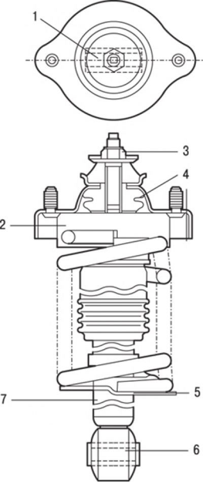
Fig. 16.20. Correct positioning of the upper support of the strut, whereby the axis of the inner tube of the lower bushing of the shock absorber should coincide with the line between the bolts of the upper support when viewed from above: 1 – inner tube of the lower sleeve; 2 – spring cup; 3 – self-locking nut; 4 – upper support of the rack; 5 – spring seat; 6 – inner tube of the lower bushing; 7 – shock absorber
5. Install the upper strut support so that the axis of the inner tube of the lower shock absorber bushing coincides with the line between the upper strut mounting bolts when viewed from above (Fig. 16.20).
6. Screw on and pre-tighten the self-locking nut.
7. Remove the special spring compressors (MB991237 and MB991239) and finally tighten the self-locking nut to the required tightening torque.
Caution: Do not use an impact wrench when tightening the special tool bolt.